
User's Manual


Installation
6 333391B
Electric Dyna-Star Cord Grip
• Cord Grip(10) (included in the kit) will accommodate
a cable with an outside diameter of 0.350 in. - 0.63
in. (9 mm - 16 mm). If the outside diameter of your
pump cable is not within this range, an appropriately
sized cord grip must be used.
• Cord Grip (10) included in kit) is used for installing
the Dyna-Star pump cord (77X528) in the Enclosure
(1).
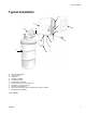
• For your convenience and reference, Mounting
Dimensions are provided on page 16 of this manual.
Install the Cable Gland (10) in a location that is most
efficient for your installation location.
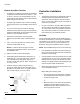
1. Determine the best path for the wiring cable
between the Dyna-Star Pump and the Enclosure
(1).
2. Use a 1 inch (25 mm) drill bit to create a hole to
install the Cable Gland Kit (10).
NOTE: If a different sized cord grip is used an
appropriately sized drill bit must be used to create
the installation hole.
3. Deburr the hole to remove sharp edges.
4. Install cable gland in drilled hole in Enclosure (1).
Install lock nut (11) on the inside of the enclosure,
over threaded end of cable gland. Tighten nut
securely to hold cable gland in place. Torque nut to
5.1 ft. lbs (7 N.m).
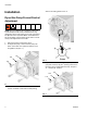
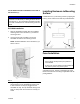
5. Feed the end of the pump wiring harness (e)
through the cable gland and into the inside of the
Enclosure (1) as shown in F
IG. 5. Tighten compres-
sion nut and torque to 3.7 ft. lbs (5 N.m).
Controller Installation
NOTE:
• The following instructions are specifically written for
installing a Graco GLC2200 Controller. These
instructions may be modified or may be unneces-
sary if you are using a different type of controller or
a PLC with your system.
• For your convenience, Controller Mounting Dimen-
sions for a Graco GLC2200 are provided on page
15 of this manual. They are provided for reference
only. Install the Controller in a location that is the
most efficient for your installation location.
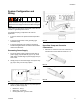
GLC2200
Graco recommends installing the GLC2200 directly to
the side of the Enclosure (1). If that type of installation is
not feasible for your location, it can also be mounted
securely to a flat surface as close as possible to the
Enclosure (see Typical Installation option J, page 3).
NOTE: The GLC2200 wiring harness cord is 5 feet long.
• If the GLC2200 is installed to the side of the Enclo-
sure (1) the wiring harness cord must be trimmed to
remove the excess length.
• If the GLC2200 is not mounted directly onto the side
of the Enclosure (1), be sure the mounting location
selected is close enough to the Enclosure to allow
sufficient cord length between the GLC2200 and the
connection points inside the Enclosure.
• Always pre-drill mounting holes in the Enclosure (1)
or your installation location.
Before drilling the mounting holes:
• Use the mounting hole dimensions provided in
the GLC2200 instruction manual as a guide to
pre-drill mounting holes
or,
• Mark the location of the two mounting holes by
positioning the GLC2200 Controller on the
installation location. Mark the location of each
mounting hole with a pencil.
FIG. 5
1
10
e
11