
User's Manual


Installation
333391B 5
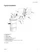
Enclosure Preparation
• Select a flat surface near the Dyna-Star pump to
install the Enclosure (1).
• Enclosure Mounting Dimensions are provided on
page 15 of this manual. They are provided for refer-
ence only and to use as a guide for pre-drilling
holes.
• 3 cord grips are included in the kit.
• 2 cord grips (12) are used for controller inter-
face and pressure switch.
• 1 cord grip (10) is used for power to the
Dyna-Star pump.
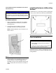
• Determine the location on the Enclosure box (1)
that best suits your application and add holes in
the box accordingly.
Controller Cord Grip Installation
• Cord Grip (12) (included in the kit) will accommo-
date a cable with an outside diameter of 0.230 in. -
0.395 in. (5.8 mm - 10.0 mm). If the outside diame-
ter of your controller cord is not within this range, an
appropriately sized cord grip must be used.
• Cord Grip (12) (included in kit) is used for installing
the GLC2200 Wiring Harness (24P314) in the
Enclosure (1).
• For your convenience and reference, Mounting
Dimensions are provided on page 16 of this manual.
Install the cord grip in a location that is the most effi-
cient for your installation location.
1. Determine the best path for the wiring cable
between the controller and Enclosure (1).
2. Use a 3/4 inch (19 mm) drill bit to create the hole to
install Cord Grip (12) in the Enclosure (1).
NOTE: If a different sized cord grip is used an
appropriately sized drill bit must be used to create
the installation hole.
3. Deburr the hole to remove sharp edges.
4. Install cord grip through drilled hole in Enclosure (1).
Install lock nut on the inside of the Enclosure, over
threaded end of cord grip. Tighten nut securely to
hold cord grip in place. Torque nut to 5.9 ft. lbs (8
N.m).
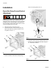
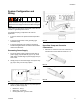
5. Feed the end of the controller wiring harness (c)
through the cord grip and into the inside of the
Enclosure (1) as shown in F
IG. 4. Tighten compres-
sion nut and torque to 5.5 ft. lbs (7.5 N.m).
Pressure Switch Cord Grip (Optional)
• Cord Grip (12) (included in the kit) will accommo-
date a cable with an outside diameter of 0.230 in. -
0.395 in. (5.8 mm - 10.0 mm). If the outside diame-
ter of your pressure switch cord is not within this
range, an appropriately sized cord grip must be
used.
• Cord Grip (12) is used for installing the Pressure
Switch Wiring Harness in the Enclosure (1).
• For your convenience and reference, Mounting
Dimensions are provided on page 16 of this manual.
Install the cord grip in a location that is the most effi-
cient for your installation location.
1. Determine the best path for the wiring cable
between the Dyna-Star Pump and the Enclosure
(1).
2. Use a 3/4 inch (19 mm) drill bit to create the hole to
install Cord Grip (12) in the Enclosure (1).
NOTE: If a different sized cord grip is used an
appropriately sized drill bit must be used to create
the installation hole.
3. Deburr the hole to remove sharp edges.
4. Install cord grip through drilled hole in Enclosure (1).
Install lock nut on the inside of the Enclosure, over
threaded end of cord grip. Tighten nut securely to
hold cord grip in place. Torque nut to 5.9 ft. lbs (8
N.m).
5. Feed the wires through the cord grip and into the
inside of the Enclosure (1). Tighten compression nut
and torque to 5.5 ft. lbs (7.5 N.m).
FIG. 4
12
1
c
12a