
User's Manual


Installation
10 333391B
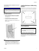
3. Connect Red (+/rd) and Black (-/bl) wires from
Dyna-Star Cable and Controller Wiring Harness to
the corresponding + and - marked DC output termi-
nals on the power supply (16) (see F
IG. 16).
Controller Connections
NOTE: Use the LEVER-NUTS
®
(26) included in this kit
to make all controller wiring connections. Instructions for
using these LEVER-NUTS
®
are provided in the follow-
ing section of this manual titled: LEVER-NUTS
®
.
GLC2200
Refer to the GLC2200 Lubrication Controller instruction
manual and GLC2200 Wiring Connector Kit instruction
manual wiring harness installation instructions.
User Supplied Controller
Refer to the Instruction Manual included with your Con-
troller for instructions related to the wiring harness con-
nections.
LEVER-NUTS
®
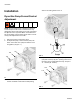
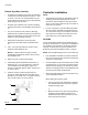
Use a LEVER-NUTS
®
(26) to connect wires.
1. Strip approximately 0.37 inches (9-10 mm) of insu-
lation from the end of each wire.
2. Push up lever (26a) on LEVER-NUTS
®
(26).
3. Insert stripped end of wire into LEVER-NUTS
®
and
push down lever (26a).
4. Push LEVER-NUTS
®
and wires neatly inside enclo-
sure, taking care to not crimp or pinch them when
enclosure door is closed.
NOTE: Depending on your application, all wires
included in the wiring harness may not be used. Blunt
cut the end of each unused wire and wrap it with electric
tape to prevent exposed wires from making contact with
any other wire.
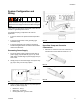
Installing Power Cord Clamp
1. Verify power to the system is disconnected and that
the power switch (3) is in the OFF position as shown
in F
IG. 21.
2. To determine the position to install the power cord
clamp (25) around the power cord, plug power cord
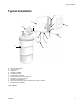
FIG. 16
FIG. 17
16
+ and -
bl
rd
rd
bl
FIG. 18
FIG. 19
FIG. 20
26a
26
26a