
User's Manual

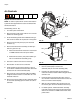

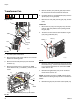
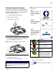
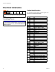
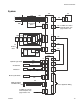

Table Of Contents
Electrical Schematics
78 333347F
Electrical Schematics
Incoming Power
Cable Identification
Use the table to identify cables and other system com-
ponents in the electrical schematics.
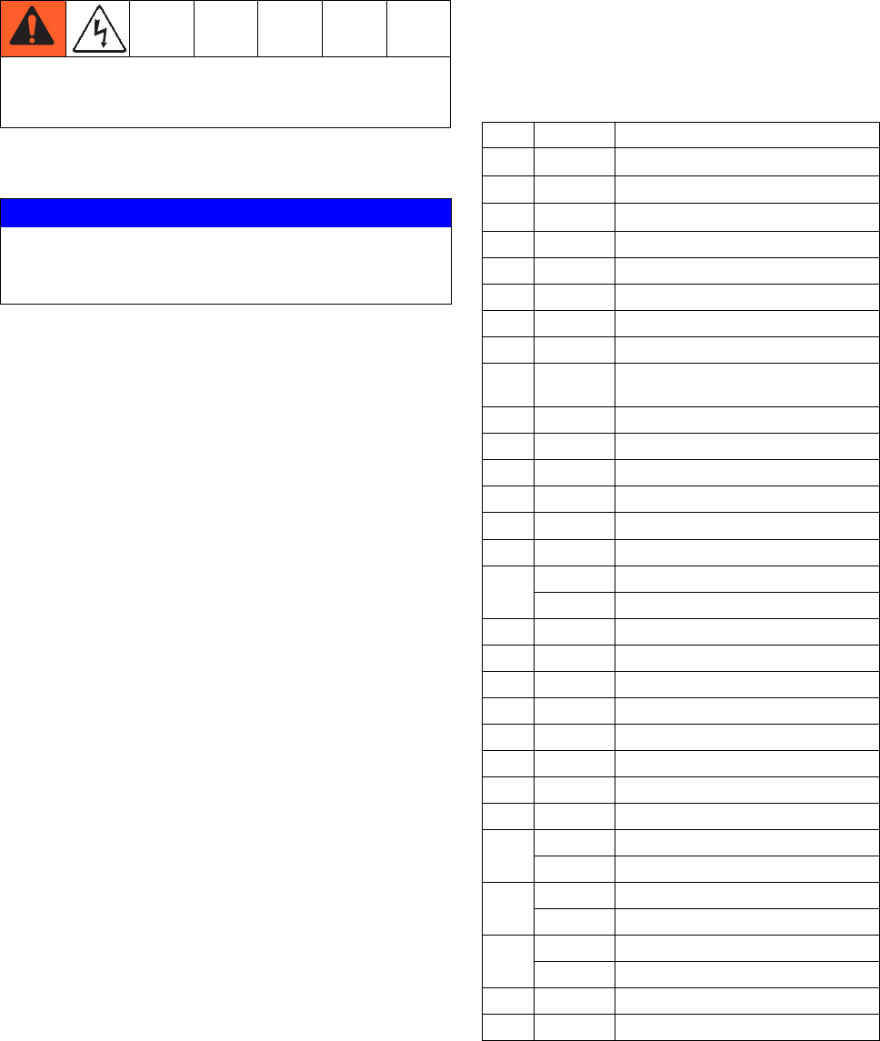
To prevent electric shock and system damage, all
electrical work must be performed by a qualified elec-
trician.
NOTICE
To prevent severe system damage, ensure main power
leads are installed correctly. See Connect Electrical
Cord on page 23.
Ref Part Description
9 --- Manifold, air assembly
20 24R041 Sensor, ultrasonic
25 24A032 Switch, reed assembly
30 24P860 ADM
86 127666 Cable, Extension
87 --- WIRE, ground
90 --- Plug, Phoenix, 8pin
103 --- Harness, MZLP #1 AWB
112 24V288 Module, MZLP with daughter
board
118 24V510 Module, MZLP
121 16T087 Cable Board
123 127768 Cable, CAN,
124 16T103 Cable Pump
125 --- Sensor, RTD, 1M
126 16T108 Cable Ultrasonic
129 --- Harness, MZLP 2, AWB
--- Harness, MZLP 2/3, AWB
135 16W035 Connector Jumper
136 --- Harness, MZLP #1 AWB
138 --- Harness, Disc AWB
140 --- Transformer
143 24V816 AWB
146 126453 Power Supply
147 --- Harness Power Supply AWB
148 --- Cable, Board, Samtec
208 24V522 Band heater, HM50
24R093 Band heater, HM25
209 24R037 Heater Rod (1500 W), HM50
24R034 Heater Rod (500 W), HM25
210 24R036 Heater Rod (1000 W), HM50
24R037 Heater Rod (1500 W), HM25
251 24R040 SWITCH, OT
1201 16T102 Light Tower