
User's Manual

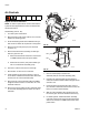
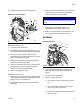

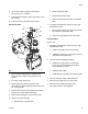
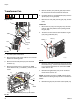

Table Of Contents
Repair
333347F 75
3. Use 10 mm socket to torque screws (509) to
95-105 in-lb (10.7-11.9 N•m).
4. Install fill cap then tighten upper hose clamp on rub-
ber housing.
5. Connect air hose and cable to the air motor.
Remove Air Motor
1. Close the bleed-type ball valve installed at the
system air inlet to relieve all air pressure in the
system.
2. Turn main power switch OFF.
3. Disconnect air line (36) from pressure relief
valve (245) then pull through metal shroud (27). See
F
IG
. 45 on page 65.
4. Remove three nuts (3) securing metal shroud (27)
in place then remove metal shroud (27).
5. Disconnect air supply line from air motor (218).
6. Remove air motor assembly:
a. Slide retaining ring (239) down.
b. Remove dowel pin (238).
c. Remove three screws (240).
d. Remove screws (8), screws (74), and bracket
(82).
7. If replacing a damaged air motor with a new fully
assembled air motor:
a. Remove three screws (211) securing air motor
tie rods (220) to base plate (219).
b. Remove tie rods (220) from air motor (218).
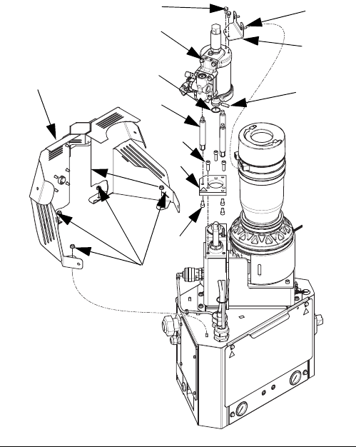
Install Air Motor
See F
IG
. 58.
1. If replacing a damaged air motor with a new fully
assembled air motor:
a. Install tie rods (220) onto air motor (218).
b. Install three screws (211) securing air motor tie
rods (220) to base plate (219).
2. Connect air motor assembly to system:
a. Install three screws (240), two screws (8),
screws (74), and bracket (82) to secure air
motor assembly to system.
b. Install dowel pin (238).
c. Install retaining ring (239) over dowel pin (238).
3. Use four nuts (3) to install melter shield (27).
4. Reconnect air supply line to air motor (218).
5. Reconnect air line (36) to pressure relief
valve (245). See F
IG
. 45 on page 65.
F
IG
. 58
WLD
220
218
238
240
211
219
239
3
27
8
82
74