
User's Manual

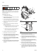
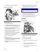

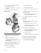
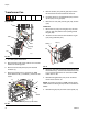
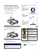
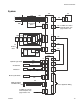

Table Of Contents
Repair
333347F 71
Replace Power Supply
Disassembly:
1. Turn main power switch OFF.
2. Remove electrical enclosure front access door (10).
3. Remove power supply (146) from power supply
bracket (145) by releasing mounting tab on the side
of the power supply. See F
IG
. 51.
4. Disconnect screw terminal connections between
power supply (146) and power supply harness (147)
according to the following table. See F
IG
. 51.
Reassembly:
1. Make connections between power supply harness
(147) and new power supply (146) according to the
following table:
2. Reattach power supply (146) to power supply
bracket (145). See F
IG
. 51.
3. Install electrical enclosure front access door (10).
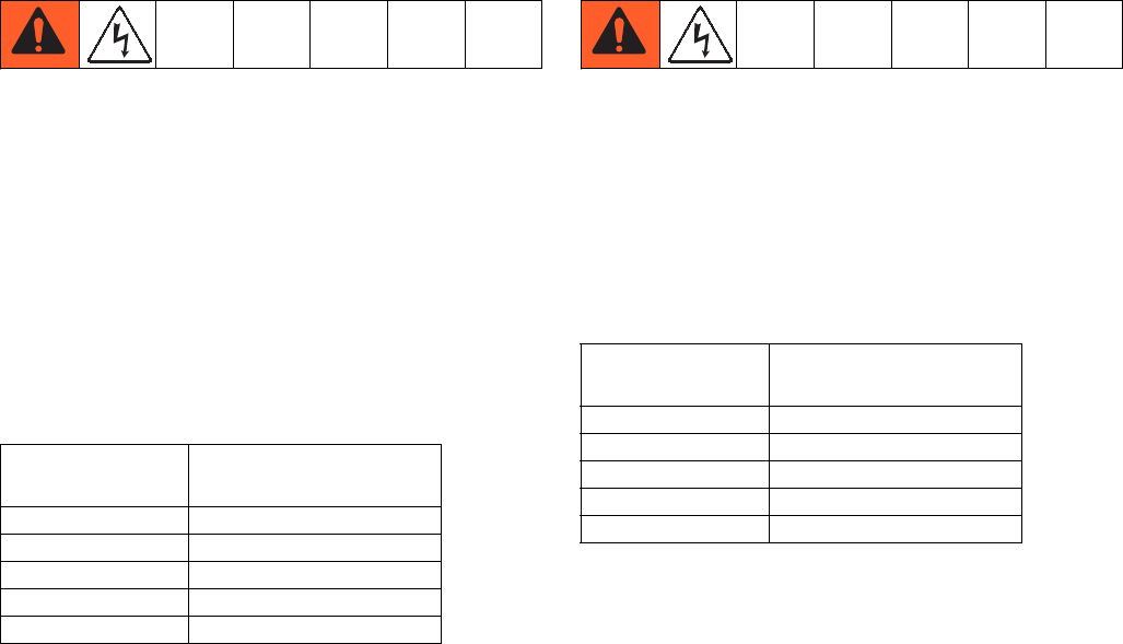
Replace Power Supply Harness
Disassembly:
1. Turn main power switch OFF.
2. Remove electrical enclosure front access door (10).
3. Disconnect screw terminal connections between
power supply (146) and power supply harness (147)
according to the following table.
4. Unplug power supply harness (147) from J1 on
AWB (143). See Electrical Schematics, page 78.
Reassembly:
1. Make connections between power supply harness
(147) and new power supply (146).
2. Connect connector (labeled AWB-J1) on power sup-
ply harness (147) to J1 on AWB (143). See Electri-
cal Schematics, page 78.
3. Install electrical enclosure front access door (10).
Power Supply
Connection
Harness Label
V+ V+
V- V-
GND GND
LL
NN
Power Supply
Connection
Harness Label
V+ V+
V- V-
GND GND
LL
NN