
User's Manual
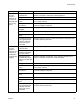
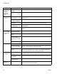
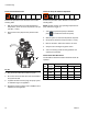
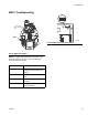
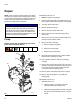
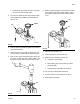
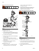
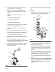
Table Of Contents
Troubleshooting
54 333347F
Flush Pressure Relief Valve
Perform this procedure when directed in the Trouble-
shooting table.
1. With the system active at the required adhesive
temperature, set the air motor air pressure to 20 psi
(140 kPa, 1.4 bar).
2. Remove the air line (36) from the pressure relief
valve.
3. Plug air line and allow the air motor to cycle.
4. Re-connect air line to relief valve and check whether
the system will stall.
5. If system still does not stall, purge ten pump cycles
of material through one applicator.
6. Repeat this entire procedure until no additional air is
expelled from the applicator.
Check the Pump Air Solenoid Operation
Perform this procedure when directed in the Trouble-
shooting table.
NOTE: System must be up to operating temperature for
pump solenoid to trigger on.
1. If the heating system and pump is disabled,
press to enable the heaters and pump.
2. Wait for system to reach the temperature setpoints.
3. Set pump air pressure to 20 psi (140 kPa, 1.4 bar).
4. Remove the 3/8 in. OD air line from the air motor.
5. Verify that air is flowing through the air line.
6. If air is not flowing, check the wiring between J13
and the pump solenoid.
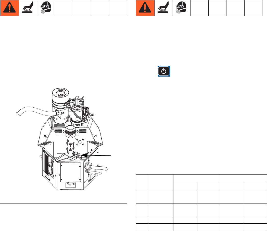
Check Heater Rod Resistance
Use the table to determine if heater elements need to be
replaced.
F
IG
. 28
WLD
36
Ref. Element
HM25 HM50
Wattage Ohms Wattage Ohms
208
Band
Heater
1250 43.5-48.5 2000 27-31
209
Melter
Rod
500 109-121 1500 36.5-40.5
210
Base Rod 1500 36.5-40.5 1000 54-61
210
Pump Rod 1500 36.5-40.5 1000 54-61