
User's Manual
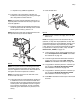
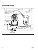
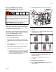
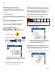

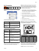
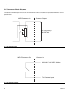

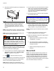
Table Of Contents
Setup
333347F 23
Connect Electrical Cord
NOTE: See Grounding section on page 17.
NOTE: The installed strain relief bushing (106) fits a
0.708-1.260 in. (18-32 mm) OD electrical cord. See F
IG
.
15. If needed, use a wrench to tighten the strain relief
bushing until it is snug on the cable.
The accessory strain relief bushing kit 24X190 is avail-
able for smaller (0.512-1.024 in, 13-26 mm) OD electri-
cal cords. See Accessories, page 100.
For 208V Electrical Circuits, see page 24.
1. Turn main power switch OFF.
2. Disconnect cable from ADM, push cable through
plastic shroud, then remove plastic shroud from sys-
tem.
3. Remove electrical enclosure access door (T). See
F
IG
. 2 on page 12.
4. Insert electrical cord through electrical enclosure
strain relief bushing (106). See F
IG
. 15.
a. Alternate electrical cord routing: using conduit,
run electrical cord from access port (X) through
hole (Y). Conduit is required when routing wires
near compressed air components.
5. Attach insulated ferrules to the end of each wire.
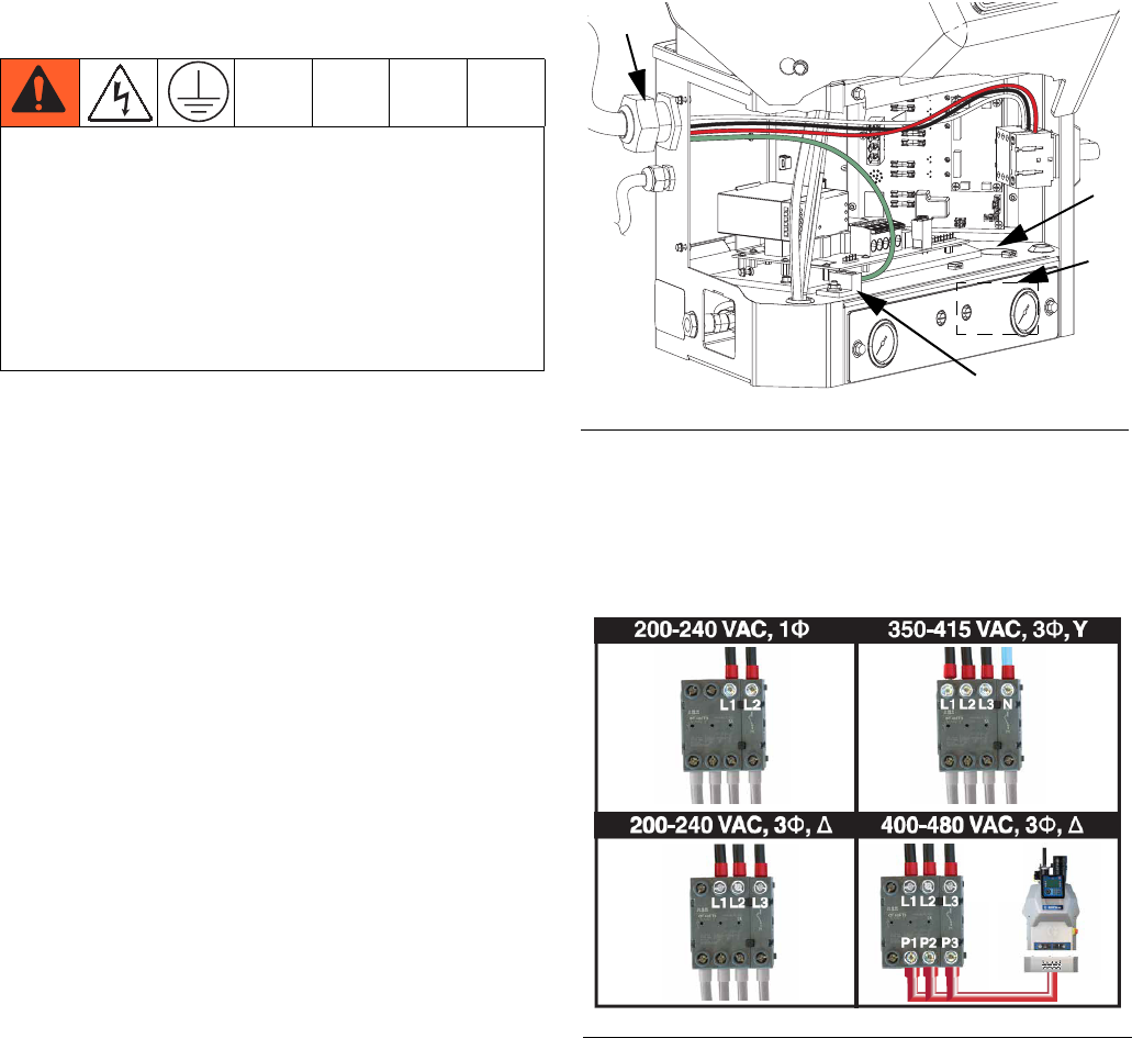
6. Connect ground wire to chassis ground (AF). See
F
IG
. 15.
7. Connect L1, L2, L3, and N as shown in F
IG
. 16. Not
all models use all 4 wires.
8. Use zip ties to secure the electrical cord to the
tie-downs located on the top of the inside of the
electrical enclosure.
9. Tighten screw-terminals to at least 10 in-lb
(1.1 N•m).
10. Install electrical enclosure door.
11. Perform Select ADM Settings on page 24 prior to
turning on heat.
Improper wiring may cause electric shock or other
serious injury if work is not performed properly. Have a
qualified electrician perform any electrical work. Be
sure your installation complies with all National, State
and Local safety and fire codes.
To reduce the risk of electric shock, perform the entire
Attach Components procedure beginning on
page 17 prior to connecting electrical cord.
F
IG
. 15
F
IG
. 16
WLD
106
AF
X
Y