
User's Manual


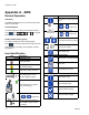
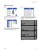


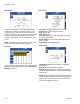
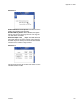
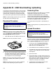
Table Of Contents
Appendix A - ADM
116 333347F
Errors
The Errors screens store a maximum of 200 errors. See
ADM Error Code Table on page 40. The errors list can
be downloaded in the USB logs. See Appendix B -
USB Downloading, Uploading on page 120.
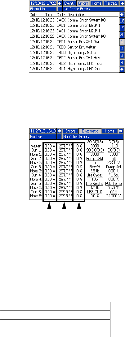
Diagnostic
This screen shows details of various items to aid in trou-
bleshooting the system. This screen can be hidden by
de-selecting “Enable Diagnostics Screen” on the Sys-
tem 3 screen. The flow rate updates every 15-20 sec-
onds with the average flow rate over the last 15-20
seconds.
The following information is displayed.
CAN: 24 VDC power supply voltage reading (18-28
VDC)
DI: System Digital Inputs
0: Not Used
1: Not Used
2: Pump Cycle Switch Up
3: Pump Cycle Switch Down
DO: System Digital Outputs
0: Pump Solenoid
1: Fill Solenoid
2: Light Tower Green Light
3: Light Tower Red Light
ISO DI: Customer Digital Inputs
0: Customer Input 1
1: Customer Input 2
2: Customer Input 3
3: Customer Input 4
ISO DO: Customer Digital Outputs
0: Customer Input 1
1: Customer Input 2
2: Customer Input 3
3: Customer Input 4
Fill: Reading of Ultrasonic Fill Sensor
• Old Fill Sensor (2400-2700 mV)
• New Fill Sensor (4200-3800 mV)
Fill Sol: Current draw of fill solenoid
• (0 mA - off)
• (150-250 mA - on)
Flow/H: Melt rate of the system
Life Cycles: total number of pump cycles over life of
system.
Life Weight: Weight of material dispensed over life of
system.
Pump Sol: Current draw of pump solenoid
• (0 mA - off)
• (150-250 mA - on)
PCB Temp: PCB Temperature on MZLP1
• 32-16°F (0-71°C)
Pump CPM: Pump cycles per minute.
USB DL%: Percentage Complete, only applies when
downloading USB data.
Diagnostic Data
A Current Draw
B RTD Reading
C Duty Cycle
A B C