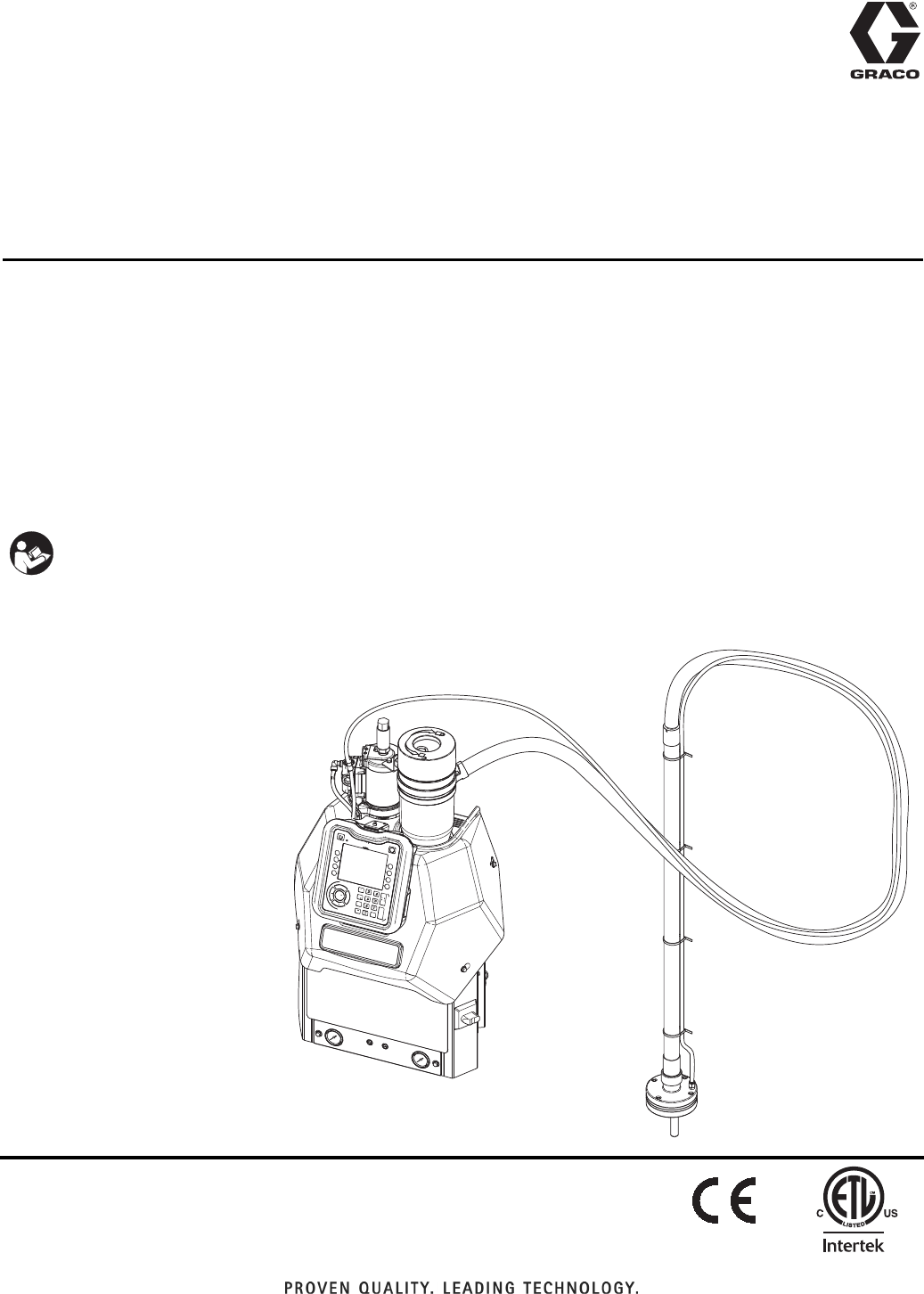
Instructions - Parts InvisiPac™ HM25 and HM50 Tank-Free™ Hot Melt Delivery System 333347F EN For delivering and dispensing hot melt adhesive pellets. For professional use only. Not approved for use in explosive atmospheres or hazardous locations. 1200 psi (8.3 MPa, 83 bar) Maximum Working Pressure 400°F (204°C) Maximum Fluid Operating Temperature 100 psi (0.
Contents Related Manuals . . . . . . . . . . . . . . . . . . . . . . . . . . . . . . . . . . . 3 Required Tools . . . . . . . . . . . . . . . . . . . . . . . . . . . . . . . . . . . . 3 Models . . . . . . . . . . . . . . . . . . . . . . . . . . . . . . . . . . . . . . . . . . . 4 200-230 VAC, 350-415 VAC HM50 Models . . . . . . . . . . . 4 200-230 VAC, 350-415 VAC HM25 Models . . . . . . . . . . . 5 400 VAC Transformer HM25 Models . . . . . . . . . . . . . . . . 6 400 VAC Transformer HM25 Models . . . . . .
Related Manuals Related Manuals Manuals are available at www.graco.com.
Models Models 200-240 VAC, 350-415 VAC HM50 Models See 400 VAC Transformer models on page 6. See 480 VAC Transformer models on page 7.
Models 200-240 VAC, 350-415 VAC HM25 Models See 400 VAC Transformer models on page 6. See 480 VAC Transformer models on page 7.
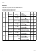
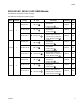
Models 400 VAC Transformer HM25 Models Model Channels Voltage 24V426 2 335-400 VAC 24V427 24V428 4 6 335-400 VAC 335-400 VAC Φ Type 3Φ / PE 3Φ / PE 3Φ / PE Frequency Max Amps 50/60 Hz 17A • 3 wire and PE • 3-Phase without Neutral • 335-400 VAC Line to Line 50/60 Hz 17A • 3 wire and PE • 3-Phase without Neutral • 335-400 VAC Line to Line 50/60 Hz 17A Frequency Max Amps Description • 3-Phase without Neutral • 335-400 VAC Line to Line • 3 wire and PE 400 VAC Transformer HM50 Models
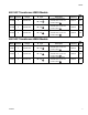
Models 480 VAC Transformer HM25 Models Model Channels Voltage 24V429 2 400-480 VAC 24V430 24V431 4 6 400-480 VAC 400-480 VAC Φ Type 3Φ / PE 3Φ / PE 3Φ / PE Frequency Max Amps 50/60 Hz 14A • 3 wire and PE • 3-Phase without Neutral • 400-480 VAC Line to Line 50/60 Hz 14A • 3 wire and PE • 3-Phase without Neutral • 400-480 VAC Line to Line 50/60 Hz 14A Frequency Max Amps Description • 3-Phase without Neutral • 400-480 VAC Line to Line • 3 wire and PE 480 VAC Transformer HM50 Models
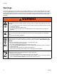
Warnings Warnings The following warnings are for the setup, use, grounding, maintenance, and repair of this equipment. The exclamation point symbol alerts you to a general warning and the hazard symbols refer to procedure-specific risks. When these symbols appear in the body of this manual or on warning labels, refer back to these Warnings. Product-specific hazard symbols and warnings not covered in this section may appear throughout the body of this manual where applicable.
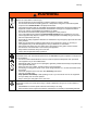
Warnings WARNING EQUIPMENT MISUSE HAZARD Misuse can cause death or serious injury. • Do not operate the unit when fatigued or under the influence of drugs or alcohol. • Do not exceed the maximum working pressure or temperature rating of the lowest rated system component. See Technical Data in all equipment manuals. • Use fluids and solvents that are compatible with equipment wetted parts. See Technical Data in all equipment manuals. Read fluid and solvent manufacturer’s warnings.
Warnings WARNING PERSONAL PROTECTIVE EQUIPMENT Wear appropriate protective equipment when in the work area to help prevent serious injury, including eye injury, hearing loss, inhalation of toxic fumes, and burns. This protective equipment includes but is not limited to: • Protective eyewear, and hearing protection.
Component Identification Component Identification G3 G2 G4 A G AD H G1 B F E WL D C D K Key: A B C D E F G G1 G2 G3 G4 H J K L M N P R S AC AD Advanced Display Module (ADM) Electrical Enclosure Pump Air Pressure Regulator Pump Air Pressure Gauge Vacuum Transfer Air Pressure Regulator Vacuum Transfer Air Pressure Gauge Shaker Tube Shaker Head Vacuum Transfer Tube Vacuum Transfer Inlet Funnel Vacuum Transfer 3/8 in.
Component Identification Heated Fluid Manifold AB Y U R AA T X W1 W2 WL D NOTE: System shown with plastic and metal shrouds removed. FIG.
Component Identification Electrical Enclosure AC P WL D AF AG FIG.
Component Identification Advanced Display Module (ADM) User Interface NOTICE BK To prevent damage to soft key buttons, do not press the buttons with sharp objects such as pens, plastic cards, or fingernails. BL NOTE: See Appendix A - ADM on page 114 for complete ADM operation details. BB BC FIG.
Component Identification Screen Components Screens Order Current date and time Operating Mode Faults, Status Melter Heating Status Melter Actual Temperature Hose and Applicator Heating Status Hose Actual Temperature Applicator Actual Temperature FIG. 6: Main Screen Components Operating Mode Description Component Status • System Off The system doesn’t have power. Inactive The heating system and pumps are disabled. Warm Up The system is heating the material to the set temperature.
Component Identification 16 333347F
Setup Setup Grounding The applicator(s) must be located no more than 25 ft (7.6 m) from the melter. The equipment must be grounded to reduce the risk of static sparking and electric shock. Electric or static sparking can cause fumes to ignite or explode. Improper grounding can cause electric shock. Grounding provides an escape wire for the electric current. The InvisiPac system is equipped with a ground terminal. A qualified electrician must ground the system using this terminal.
Setup 3. Adjust the funnel inlet: G3 23 81 92 WL D a. Remove plug (23) and insert the provided 5/16 in. nut driver (92) through the access hole in the back of the system. Loosen the band clamp (81) two turns. WL D FIG. 8: Lifting Strap b. Rotate the funnel inlet (G3) and re-tighten the band clamp (81). 2. Place the base system in the desired operating location and orientation. See Location, page 17.
Setup NOTE: In the following steps, when routing the vacuum transfer hose, ensure there are no tight coils, turns, or dips in the vacuum hose. These will inhibit optimal functioning of the vacuum transfer system. NOTE: Maximum vacuum hose length is 30 ft (9.1 m). Use horizontal hose routing as much as possible. The vacuum hose must not rise more than 10 ft (3.0 m), measured from the vacuum inlet. Any vertical rise will lower the maximum flow rate of the vacuum transfer system. 6. Route the 1.3 in.
Setup f. 14. Install heated hoses, see FIG. 11: To reduce the risk of fire and explosion, only use Graco heated hoses with the InvisiPac system. Use of non-Graco hoses will void agency approvals. N Applicator 247 68 g. Locate MZLP (AA) connector marked with same number as the hose fluid outlet port. Remove that connector cover then install connector from heated hose. See FIG. 11. h. Repeat the procedure for the remaining channels. Use the bottom melter ports first to ease installation. i. W1 AA FIG.
Setup 19. Close the ball valve. d. Repeat for any additional applicators. 16. If necessary, set up the pattern controller (not included) to control opening and closing of the applicator. See pattern controller manual. NOTE: The system controls applicator heating only. A separate pattern controller must be set up to open and close the applicator. WL E 17. Install the supplied air inlet bleeding ball valve and air filter kit (Graco Part No. 24R707) at the 1/4 NPT female system air inlet (J). See FIG.
Setup Recommended Air Setup Main Air Line No dips in vacuum transfer hose Air In: Less than 50 ft (15.2 m): 3/8 in. More than 50 ft (15.2 m): 1/2 in. 80-100 psi (5.5-6.8 bar, 0.55-6.8 MPa) 30 scfm capacity. Air In: 3/8 in., 100 psi (6.8 bar, 0.68 MPa), 30 scfm capacity Ensure funnel air is connected Air Filter/Ball Valve at System Air Inlet (Graco Kit 24R707, included) Vacuum Regulator set to 70 psi (4.8 bar, 0.48 MPa) Pump Vacuum: 40 - 80 psi (2.8-5.5 bar, 0.28-0.
Setup Connect Electrical Cord NOTE: See Grounding section on page 17. 5. Attach insulated ferrules to the end of each wire. 106 Improper wiring may cause electric shock or other serious injury if work is not performed properly. Have a qualified electrician perform any electrical work. Be sure your installation complies with all National, State and Local safety and fire codes.
Setup 208V Electrical Circuits NOTE: An incorrect RTD setting will cause the system to be incapable of maintaining the temperature setting. For 208V electrical supply, a qualified electrician can install a 208V to 240V step-up transformer to improve startup times. Transformer Sizing Minimum transformer rating can be calculated by taking transformer output voltage times the ADM breaker setting.
Setup 6. On the Advanced 2 screen, set the temperature and mass units. 9. Press to switch from the Setup screens to the Operation screens. Use , , , and to navigate between screens. 10. On the Targets screen, use next to and , shown , to adjust system melter setting. Also, the desired temperature setting can be typed in using the numeric keypad. 7. To setup the optional Schedule function, see Schedule on page 33.
Setup NOTE: Alternatively, use the physical up and down 11. On the Targets screen, adjust heated hose and applicator temperature settings: arrow push-buttons on the ADM keypad until is next to the temperature setting to change then use the numeric keypad to enter the desired temperature. NOTE: InvisiPac is a high powered tank-free system that delivers heat faster than traditional tank systems.
Setup PLC Connection A PLC can control and monitor all items shown in the dropdown menus on the System 1 screen in the Setup screens. NOTE: The InvisiPac system ships with two screw-terminal connectors that plug into MZLP connectors H1 and H2. Connectors are located in a bag on the inside of the electrical enclosure front access door. To replace the connectors, order kit 24P176. 1.
Setup PLC Connection Block Diagrams The following block diagrams show how to connect customer inputs and outputs to the InvisiPac MZLP. For convenience, each InvisiPac ships with connector kit 24P176. If a connector is lost or damaged, order kit 24P176 for replacements. MZLP Customer In Customer Output Vin (no polarity) 30 VDC Max FIG. 18: Customer Input MZLP Customer Out Customer In 250 VAC, 0-30 VDC, 2A Max To Customer Input FIG.
Operation Operation Initial Startup and Prime Heating and dispensing hot melt adhesive may create potentially harmful vapors. Read material manufacturer’s warnings and material MSDS to know specific hazards and precautions. Ventilation of the work area may be required. NOTE: See Appendix A - ADM on page 114 for detailed ADM information. NOTICE To prevent damage to soft key buttons, do not press the buttons with sharp objects such as pens, plastic cards, or fingernails.
Operation 6. Use pump air pressure regulator (C) to adjust pump air pressure to 0. 10. On new systems only: After the melter has reached 250°F (121°C) and the funnel is filled with pellets, set the melter temperature back to the desired operating temperature. See Select ADM Settings on page 24 for instructions. 11. Use separate pattern controller to open the applicators and keep them open. NOTICE E C FIG. 20 7.
Operation It is recommended to maintain a minimum flow rate of 1.5 lb/hour to prevent material from melting within the feed cap and funnel. If production rate is below 1.5 lb/hour or system sits at temperature without dispensing for extended periods of time, use manual refilling with caution. System flow rate can be monitored by enabling the Diagnostic screen. 1. On the System 3 screen (in the Setup screens), select “Manual” from the Refill mode dropdown. 5.
Operation 4. If not already set, use vacuum transfer air pressure regulator (E) to adjust vacuum transfer air pressure setting to 40-100 psi (280-690 kPa, 2.8-6.9 bar). Recommended setting is 60 psi (414 kPa, 4.1 bar). e. Verify applicators are closed. 4. Press to enable the heaters and pump. NOTE: If using the Schedule function, the heaters and pump will be enabled automatically at the set time.
Operation Shutdown Enable Schedule Function Press The Schedule function is automatically enabled when values are entered in the Schedule screen. To disable a to disable the heaters and pump. The screen will say “Inactive”. If using the Schedule function, the heaters and pump will be disabled automatically at the set time. You will not need to press if using the Schedule function unless you wish to disable the heating system before the set time.
Operation Drain the System 12. Wait until system stops draining or at most 10 minutes. NOTE: There will be some residual adhesive in the system. NOTE: The system must be drained prior to flushing and prior to some maintenance and repair procedures. 1. On the System 3 screen (in the Setup screens), change the Refill Setting to “Manual”. 13. When done performing the procedure that required draining the system, set Refill Setting back to “Auto” on the System 3 screen.
Operation 5. On the System 3 screen (in the Setup screens), verify the Refill Setting is set to “Manual”. 12. If heating system is disabled, press to enable the heaters and pump. 13. Wait for the melter temperature to reach the hot melt cleaning fluid manufacturer’s recommended temperature. NOTE: The pump will not run because the system air inlet ball valve is closed. 14.
Operation 25. Install fill cap onto melter rubber housing. 26. Slide funnel assembly through air motor bracket then tighten clamp. 27. On the System 3 screen (in the Setup screens), set the Refill Setting to “Auto”. Operation Tips to Minimize Charring Set the Pump Idle Time to System Inactive function on the System 3 screen to lowest value that will not interfere with normal operation. This feature automatically disables the heating system if the pump is idle for longer than the preset amount of time.
Maintenance Maintenance 6. Insert allen wrench through the outlet filter cap to lift outlet filter (236) out of the system. 7. Discard outlet filter assembly. Replace Outlet Filter The outlet filter is designed to prevent small contaminants from entering the hoses and applicators. Inspect filter regularly. Replace the filter after flushing and when you change the adhesive used in the system. 8. Place o-rings (232, 237) provided with new outlet filter onto new outlet filter (236). 9.
Maintenance 4. When the melter temperature is the desired temperature, turn main power switch OFF. 9. Slide new screen (213) into melter base manifold (201). 5. Disconnect cable from ADM, push cable through plastic shroud, then remove plastic shroud from system. 10. Install filter cap (215) then use a 1 in. socket to tighten. 6. Place a piece of cardboard beneath the inlet filter cap (215) to route fluid away from system into a waste container in the event the adhesive is a fluid. 7. Use 1 in.
Maintenance Filter Maintenance Guidelines* Environmental Classification Clean Pump inlet filter Pump outlet filter Applicator manifold filter System air filter Solenoid exhaust filters Feed funnel filter Feed funnel inspection/cleanout Moderate Dusty Replace filter Replace filter Replace filter every six every four every two months months months * These recommendations are service level guidelines - actual service levels required in your factory will vary based on environmental and operating conditions
Troubleshooting Troubleshooting To avoid injury due to unexpected machine operation initiated by a remote controller, disconnect the customer I/O cable from the system prior to troubleshooting. ADM Error Code Table When an error occurs, press nance screen and press to acknowledge the error. If a Maintenance error occurs, navigate to the Mainteto clear the error. The last digit of the error code indicates the melter, applicator (gun), or hose to which the error applies.
Troubleshooting Code A3MF A4D0 A4D_ A4D_ A7D0 Description High Fan Current, Transformer High Current Melter High Current Hose X High Current Gun X Unexpected Current Type Deviation Cause Transformer fan is greater than 600mA. Solution Replace transformer fan. Alarm Defective or shorted to ground on the band heater or rod heater. Defective or shorted to ground on the hose power wires. Defective or shorted to ground on the heater rods in applicator manifold. Unexpected current flow to melter.
Troubleshooting Code CAC_ 1=MZLP 1 2=MZLP 2 3=MZLP 3 Description Comm Error Module Type Alarm Cause System not responding to ADM. CACX Missing DB Alarm System not acknowledging the daughter board. DADX Pump Runaway Alarm Pump is trying to feed adhesive, no adhesive to feed. DDDX Pump Diving Deviation Worn or damaged pump seals Pump is trying to feed adhesive, no adhesive to feed. Worn or damaged pump seals No signal from air motor sensor.
Troubleshooting Code L8FX Description Refill timeout Type Alarm Cause Melter did not receive enough adhesive pellets for flow rate. M8MF High Temp Run- Deviaaway, Transtion former At the current rate of temp rise, the transformer will over heat in 15 minutes or less. MMUX USB Log Full MNDX Pump Maintenance Due Low Temperature, Melter USB logs full. Data loss will occur if not downloaded. Cycles are greater than user set maintenance interval.
Troubleshooting Code T4D0 Description High Temp Melter Type Alarm Cause Solution Melter continues to raise above the set- Check that RTD is seated in melter correctly. point. Check that overtemperature switch is plugged in and check switch resistance. The switch resistance should be near 0 Below 400°F (204°C). Check melter heaters’ resistance to ground. Replace heater if a heater is shorted to ground. T4D_ High Temp Hose Alarm Hose continues to raise above the setpoint.
Troubleshooting Code T8D_ T8D0 Description No Temp Rise in Hose (all zones) No Temp Rise in Melter (all zones) Type Alarm Alarm Cause Solution Temperature reading does not change. Check fuses F5 and F6 (channels 1, 3, 5) or F9 and F10 (channels 2, 4, 6) on the MZLP that controls the error channel. Defective heater wires in hose. Replace heated hose. NOTE: Defective heaters wires in the hose can also cause the no current error. Heated hose electrical connector or wires are defective.
Troubleshooting Mechanical and Electrical Troubleshooting Problem Cause Solution Refill Timeout Error The system was unable to refill in less than 30 seconds. Check hopper for adequate material and material blocking. Verify the vacuum transfer system air pressure is 40-80 psi (60 psi recommended) and that air is flowing to the feed wand while attempting to refill. Restart system.
Troubleshooting Problem Cause Solution Level Sensor Error Failure of the level sensor (20) or sensor cable 16T108 (J14 to level sensor (20)). Check sensor cable J14 to level sensor (20). Enable Diagnostic screen on ADM then check sensor readings on the Diagnostic screen. Sensor readings should be about 4.3V if melter is completely empty (melter passage holes are visible). The normal operating range is 3.8 to 4.3V. If the sensor is reading more than 4.
Troubleshooting Problem Cause Solution USB Log Full The InvisiPac system will display this notification when the USB data logs reach 90% full. To prevent data loss, download system data. See Appendix B - USB Downloading, Uploading on page 120. The InvisiPac system is displaying pump runaway or pump diving.
Troubleshooting Problem Cause Solution Unable to achieve published melt rate at the desired adhesive temperature. 1. If the cycle rate is below (11 cpm - HM25, 22 cpm - HM50) and the The InvisiPac system system is still running away increase the InvisiPac system monitors temperature temperature in small increments over the current set point, leave within aluminum mass hoses and applicators at desired set point. of melter (202). As melt rates exceed 20 lb/hr a 2.
Troubleshooting Problem Cause Solution Slow start-up time or system takes longer than 10 minutes to startup Wrong setting in ADM breaker setup. Wrong breaker setting on ADM in the breaker setting in the setup screen. Low incoming voltage. Incoming voltage should be 200-240VAC for a 230 volt unit and 380400 VAC for a 400 volt unit. Heater rod defective. Melter and gun manifold. Measure and check heater rods in melter or applicator. See applicator manual. See Check Heater Rod Resistance, page 54.
Troubleshooting Problem Cause Solution No adhesive or incorrect amount of adhesive output when all dispense modules are triggered Plugged applicator manifold filter. Replace applicator manifold filter. Graco applicator manifold filter in bottom of manifold or inline filter on other applicators. Clogged hose. Flush or replace hose. Defective solenoid valve. Check that correct voltage is input into solenoid valve. If voltage is correct, replace solenoid. No signal from control to solenoid.
Troubleshooting Problem Cause Solution Adhesive flowing out of one/some applicators when not triggered Failed valve in the open position. Replace dispense module. Adhesive pressure too high. Reduce air pressure to air motor. Applicator will not heat. Heat rod failure in applicator manifold. Check resistance on heater rods. Repair applicator manifold if heater rods measure open. Loose cable connection at system or manifold. Check cable connections on both ends of the hose. RTD failure.
Troubleshooting Problem Cause Solution Static shock when touching shaker or adhesive bin. Ground wire not in place on shaker assembly. Some adhesives, flow rates, and ambient conditions can cause excessive static buildup on the shaker tube. Attach a ground wire from the shaft of the shaker unit to a true earth ground. Order shaker grounding kit 24R708. Adhesive not dispensing at the correct time. Dispense modules opening at the wrong time.
Troubleshooting Flush Pressure Relief Valve Check the Pump Air Solenoid Operation Perform this procedure when directed in the Troubleshooting table. Perform this procedure when directed in the Troubleshooting table. 1. With the system active at the required adhesive temperature, set the air motor air pressure to 20 psi (140 kPa, 1.4 bar). NOTE: System must be up to operating temperature for pump solenoid to trigger on. 1. If the heating system and pump is disabled, 2.
Troubleshooting Red Yellow Green MZLP Troubleshooting 7 89 56 J3 234 01 MZLP ti20348a FIG. 30: MZLP Diagnostic LED Location WL D FIG. 29: MZLP LED Signals NOTE: The MZLP LED is located on the inside of the electrical enclosure. To view, remove the electrical enclosure front access door. Signal Description Green On MZLP is powered up and input voltage is within operating conditions. Yellow On Internal communication in process Red Solid MZLP failure. See troubleshooting table.
Repair Repair NOTE: Some procedures require special tools. Read through each procedure prior to beginning it to ensure you have the required tools to complete the entire procedure. Order any required tools and have them on hand prior to beginning the procedure. NOTICE Disassembly (see FIG. 31): 1. Flush the system. See page 34. 2. Close the bleed-type ball valve installed at the system air inlet to relieve all air pressure in the system. 3. Turn main power switch OFF.
Repair c. Install piston valve (222) onto piston rod (223). Torque to 24-30 ft-lb (33-41 N•m). 2. To protect the seals from the sharp threads, place seal installation tool 15B661 into the throat bore. See FIG. 32. 6. Slide throat bearing (233) over the piston rod (223). Use socket and tap with a rubber mallet to press throat bearing (233) into place and seat the throat u-cup. 235 15B661 203 233 ti20877a FIG. 32 3. Push the piston rod assembly (223) into the melter outlet manifold (203). 4.
Repair Replace Pump Inlet Housing Checks without a socket to install and tighten foot valve (230) onto melter. 2. Apply anaerobic thread sealant on threads of four bolts (246) and connect pump to melter outlet. Torque to 12-18 ft-lb (16-24 N•m). Replace Pump Cylinder Seals and Piston Seals 203 218 246 235 227 228 233 229 231 233 230 224 226 222 234 WL D 239 FIG. 35 Disassembly (see FIG. 35): 203 1. Flush the system. See page 34. 2.
Repair 5. Remove air lines from relief valve (245) and air motor (218) See FIG. 31 on page 56. 14. Remove and discard cylinder seals (217). See FIG. 37. 6. Remove nuts (3) securing melter shield (27) in place then remove melter shield. See FIG. 31 on page 56. Reassembly: 1. Apply grease to seals (217) then install new cylinder seals (217) onto cylinder (216). See FIG. 37. 7. Remove air motor assembly. See FIG. 31 on page 56: a. Remove retaining ring (239). 1303 b. Remove dowel pin (238). c.
Repair Melter 6. Remove screws (8) then remove electrical enclosure front access door (10). Remove Melter Assembly 7. Disconnect heater rod wires from J4 connector on AWB board. 8. Remove the air tube (36) from the relief valve (245). Pull the air tube from the metal shroud (27). FF 9. Remove nuts (3) on the back metal shroud (27) then remove shroud. 10. Remove fabric melter insulator (53). 30 81 11. Loosen screw (AA) then remove sensor (125). See FIG. 42, page 63. 53 29 12.
Repair 21. Remove all heater wires from the following terminals. Pull wires up through the rubber grommet on the top of the electrical enclosure (1). 5. Group the 4 sets of heater wires together and run them through the grommet on the top of the electrical enclosure (1). Connect wires as noted below.
Repair Replace Band Heater 8. Locate the J4-1 and J4-2 wires in AWB board and remove wires. 8 9. Pull wires up through grommet (63) on top of the electrical enclosure (1). Clip any wire ties that hold the wires in place. F 10. Continue loosing screw (AA) then slide band heater (208) up to remove. 80 Reassembly (see FIG. 41): 53 208 1. Install band heater (208) on the melter with the opening and screw facing the front of the system in alignment with the sensor port. 2. Install sensor (125). 3.
Repair Reassembly (see FIG. 42): Replace Band Heater Temperature Sensor 1. Route new harness wires through grommet (63) in the top of the electrical enclosure. 2. Connect wire connectors to over-temperature switch (251). See FIG. 43 on page 64. 53 3. Place band heater temperature sensor (125) in melter. 4. Tighten screw (AA). NOTE: Screw should lightly squeeze the temperature sensor to hold it in place. It should not bend the sensor. 5. Connect new harness to MZLP connector labeled J5.
Repair Replace Heater Over-Temperature Switch 5. Feed ADM cable through shroud then install shroud and connect cable to ADM. 6. Open system air inlet ball valve. 7. Turn main power switch ON. 251 Replace Heater Rod 255 206 ti21052a FIG. 43 210 Disassembly (see FIG. 43): 1. Close the bleed-type ball valve installed at the system air inlet to relieve all air pressure in the system. 2. Turn main power switch OFF. 206 210 3. Disconnect cable from ADM then remove shroud. 4.
Repair 4. If removing the pump heater rod (210): a. Remove the air tube (36) from the relief valve (245). Pull the air tube through the metal shroud (27). b. Remove nuts (3) then remove shroud (27). 5. If replacing pump heater rod (210), feed ADM cable through shroud then install shroud and connect cable to ADM. 6. If installing the pump heater rod (250), install the metal shroud (27): a. Place metal shroud on system. 5. Remove electrical enclosure front access door (10). See FIG. 41, page 62. b.
Repair 6. Use crescent wrench to remove melter fluid pressure relief valve (245). See FIG. 45. 7. Use an o-ring pick to remove o-ring (244). 8. Install o-ring (244) into manifold. NOTICE To prevent damage to o-ring, ensure o-ring is seated properly prior to moving to next step. 9. Thread new fluid pressure relief valve (245) into manifold. See FIG. 45. Once hand-tight, use crescent wrench to tighten. 10. Use nuts (3) to install metal shroud. 11. Connect air tube to pressure relief valve. 12.
Repair Multi-Zone Low Power Temperature Control Module (MZLP) Replace MZLP Fuse Fuse Part 24V510 MZLP Fuses MZLP Identification F1, F2 250VAC, 25A, fast acting, white, 0.25 in x 1.2 in F3-F10 250VAC, 8A, fast acting Fuse Kits 24V510 Kit MZLP Description 24V289 24V510 Includes standard clear fuses. 24X480 Includes ceramic fuses used for food industries. 1. Turn main power switch OFF. 2. Remove electrical enclosure front access door (10).
Repair Replace MZLP 2. Apply channel label stickers to new MZLP. See FIG. 47. 3. Use four screws (114) to install MZLP (112) to electrical enclosure (1). Disassembly: 4. Reconnect cables to MZLP (112). 1. Turn main power switch OFF. 2. Remove electrical enclosure front access door (10). 3. Disconnect heated hose electrical connectors from outside of MZLP (112). 4. Note location of each cable, then unplug all cables from the MZLP (112) that will be replaced. See FIG. 47. 5.
Repair Reassembly: 1. Plug new daughter card (112a) into the MZLP (112). 2. Use screws (112b) to secure daughter card to MZLP (112). 3. Connect cables to new daughter card (112a). NOTE: Do not force the electrical connection. Minimal force is required to seat the connector. If resistance is felt, stop and verify the connector orientation. NOTE: If unable to determine connector location, see Electrical Schematics on page 78. 3.
Repair Reassembly: Replace AWB 1. Use two screws (144) to secure power supply bracket (145) to new AWB (143). See FIG. 51. 2. Mount power supply (146) to power supply bracket (145). See FIG. 51. 131 3. Connect connector (labeled AWB-J1) on power supply harness (147) to J1 on AWB (143). See Electrical Schematics, page 78. 144 145 4. Use two screws (131) to install AWB (143) to electrical enclosure (1). See FIG. 51. 146 5. Reconnect cables to AWB (143). NOTE: Do not force the electrical connection.
Repair Replace Power Supply Replace Power Supply Harness Disassembly: Disassembly: 1. Turn main power switch OFF. 1. Turn main power switch OFF. 2. Remove electrical enclosure front access door (10). 2. Remove electrical enclosure front access door (10). 3. Remove power supply (146) from power supply bracket (145) by releasing mounting tab on the side of the power supply. See FIG. 51. 3.
Repair Air Controls 8 405 402 9 Replace Air Control Solenoids NOTE: In order to replace the air control solenoids, the system must be tipped back to access underneath the electrical enclosure. Disassembly (see FIG. 52): 1. Turn main power switch OFF. 1 2. Disconnect plug from power outlet or turn off circuit breaker for incoming power. WL D 3. Close the bleed-type ball valve installed at the system air inlet to relieve all air pressure in the system. FIG. 52 FF 4.
Repair 3. Place one small crescent wrench on the brass part of the gauge then use a second small crescent wrench to tighten the air fitting (403b). 6. Install electrical enclosure front access door. Replace Air Control Gauge NOTICE 8 403a 403c In the following step, do not overtighten the two nuts (403a). Overtightening may cause the gauge to break. 403 9 4. Orient gauge as desired then tighten two nuts (403a) to secure gauge (403) in place. 5.
Repair d. Torque pilot valve to 95-105 in-lb (10.7-11.9 N•m). Replace Air Valve 218 4. Replace bottom pilot valve (511): 507 29 218 512 6 509 FIG. 57 Disassembly (see FIG. 57): 511 1. Close the bleed-type ball valve installed at the system air inlet to relieve all air pressure in the system. 2. Turn main power switch OFF. WL D FIG. 56: Bottom Pilot Valve 3. Loosen clamp on air motor bracket (528) then remove funnel assembly (61). a. Remove cover (29) and insulation (6). 4.
Repair b. Remove dowel pin (238). 3. Use 10 mm socket to torque screws (509) to 95-105 in-lb (10.7-11.9 N•m). 4. Install fill cap then tighten upper hose clamp on rubber housing. 5. Connect air hose and cable to the air motor. Remove Air Motor 8 74 218 82 27 c. Remove three screws (240). d. Remove screws (8), screws (74), and bracket (82). 7. If replacing a damaged air motor with a new fully assembled air motor: a. Remove three screws (211) securing air motor tie rods (220) to base plate (219).
Repair Transformer Fan 5. Remove screws (157) and fan grill (154). Pull two fan wires down into the transformer enclosure. 6. Cut three zip ties on corrugated tube (167) and two zip ties (161) on fan grill (154). Replace Fan 7. Remove four nuts (158), rear fan grill (170), and fan (155). 1 Install Fan 1. Mount new fan (155), rear fan grill (170), and nuts (158) on grill (154) with the arrow pointing toward the grill (154). 2.
Repair Software Update Procedure When software is updated on the ADM the software is then automatically updated on all connected GCA components. A status screen is shown while software is updating to indicate progress. 1. Turn system main power switch OFF. NOTE: When the screen turns on, you will see the following screens: First: Software is checking which GCA modules will take the available updates. 2. Remove ADM from bracket. 3. Remove token access panel.
Electrical Schematics Electrical Schematics Cable Identification To prevent electric shock and system damage, all electrical work must be performed by a qualified electrician. Incoming Power Use the table to identify cables and other system components in the electrical schematics. Ref 9 Part --- Description Manifold, air assembly 20 24R041 Sensor, ultrasonic NOTICE 25 24A032 Switch, reed assembly To prevent severe system damage, ensure main power leads are installed correctly.
Electrical Schematics System 30 143 140 138 AWB J2 L1 N N L2 5L3 6T3 W2 L3 3L2 4T2 W3 1L1 2T1 W1 1 2 3 4 5 W4 GND ADM J9 1 2 3 4 5 123 1 2 3 4 5 1 2 3 4 5 GND 208 Band J7 Transformer Option GB1 210 209 210 Pump Melter Base TEMP TEMP TEMP FAN - TEMP FAN - FAN + FAN + 90 J4 1 2 3 4 5 6 7 8 1 2 3 4 5 6 7 8 J5 L1 L2 L3 GND L1 L2 L3 GND J8 1 2 3 4 5 1 2 3 4 5 148 L1 L2 L3 GND 136 J6 L1 L2 L3 GND 87 147 Ground Stud DC OK DC OK -V -V +V +V 129 To MZLP #2 4
Electrical Schematics 480VAC Transformer Option 143 AWB J2 W1 L1 N N P3 W2 L2 5L3 3L2 6T3 P2 W3 4T2 P1 W4 1L1 2T1 L3 GND J7 PTC TEMP TEMP TEMP FAN FAN + TEMP FAN FAN + GB GND GB1 Typical Hose / Applicator Wiring 112 MZLP1 J8 GUN HEATER 80 T° GUN RTD OVER TEMP GND HOSE HEATER T° HOSE RTD A A B B C C D D E E F F G G H H J J K K L L 333347F
Electrical Schematics 2nd and 3rd MZLP Options 135 1 2 3 4 5 6 333347F J5 1 2 3 4 5 6 118 118 MZLP3 MZLP 2 J3 1 2 3 4 5 1 2 3 4 5 121 1 2 3 4 5 112 MZLP 1 J3 J6 1 2 3 4 5 1 2 3 4 5 J3 1 2 3 4 5 121 1 2 3 4 5 1 2 3 4 5 81
Line Air Inlet 82 Level Air Sensor Level Sensor Restrictor Under Control Box Safety Pop Off Valve Refill Gauge Refill Control Solenoid Air Control Manifold Air Motor Control Solenoid Air Motor Gauge Feed Wand Air Motor Pressure Relief Valve Optional Ramp Up/Down Controller Air Schematic Air Schematic NOTE: Install an optional ramp up/down controller to limit air to the air motor and slow down the system dispense rate.
Parts Parts InvisiPac Systems System Parts, Page 1 of 3 1 Apply door gaskets (11) to door (10) per layout diagram. 2 Apply pipe sealant to all non-swiveling pipe threads. 3 Bottom sensor (20) out then back off 1/2 turn. 4 Lubricate all seals and o-rings with water resistant grease. 5 Torque to 5-11 ft-lb (7-15 N•m). 6 Torque to 8-10 in-lb (0.9-1.1 N•m).
Parts System Parts, Page 2 of 3 68 8 67 69 74 66 82 5 86 20 8 49 7 3 72 73 42 41 74 40 69 88 3 5 63 62 87 69 89 1 61 54 4 85 81 8 79 63 80 WL D 9 43 8 84 333347F
Parts System Parts, Page 3 of 3 34 48 in. (1219 mm) 57 35 48 in. (1219 mm) 34 16 in. (406.4 mm) 86 91 34 48 in. (1219 mm) 49 35 48 in. (1219 mm) 34 8 in. (203 mm) 78 32 77 76 34 2 in. (50.8 mm) 24 39 WL D 55 333347F 36 13 in. 330.
Parts System Parts Quantities 24V202 24V199 24T920 24V203 24V200 24V423 24V429 24V426 24V424 24V430 24V427 24V425 24V431 24V428 6 Channel 24T919 HM25 4 Channel 24V198 2 Channel 24V201 6 Channel 24T918 2 Channel HM50 4 Channel 1 1 1 1 1 1 1 1 1 1 1 1 1 1 1 1 1 1 3 115942 NUT, hex, flange head 8 8 8 8 8 8 8 8 8 8 8 8 8 8 8 8 8 8 4 167002 INSULATOR, heat 4 4 4 4 4 4 4 4 4 4 4 4 4 4 4 4 4 4 1 1 1 1 1 1 1 1 1 1 1 1
Parts Quantities 24T919 24V202 24V199 24T920 24V203 24V200 24V423 24V429 24V426 24V424 24V430 24V427 24V425 24V431 24V428 6 Channel 24V198 2 Channel 24V201 6 Channel HM25 4 Channel 24T918 2 Channel HM50 4 Channel 1 1 1 1 1 1 1 1 1 1 1 1 1 1 1 1 1 1 BUSHING, strain relief 2 2 2 2 2 2 2 2 2 2 2 2 2 2 2 2 2 2 GROMMET, tube 1 1 1 1 1 1 1 1 1 1 1 1 1 1 1 1 1 1 1 1 1 1 1 1 1 1 1 1 1 1 1 1 1 1 1 1 1 1 1 1 1 1
Parts Quantities 1 1 1 1 1 1 1 1 1 1 1 24V428 1 24V431 1 24V425 1 24V427 1 24V430 1 24V424 1 6 Channel 24V426 24V200 1 2 Channel 24V429 24V203 --- 24T920 BRACKET, funnel, HM25 24V199 CLAMP, hose, spacer 24V202 ----- 24T919 81★ 82† 24V198 Description CLAMP, hose, spacer 24V201 Ref Part 80★ --- 6 Channel 24T918 2 Channel HM25 4 Channel 24V423 HM50 4 Channel 2 2 2 2 2 2 2 2 2 1 1 1 1 1 1 1 1 1 83 123986 BRACKET, HM50, funnel, 1 mounting FITT
Parts Electrical Enclosure MZLP 3 MZLP 118 4 113 114 112a 3 118 113 114 106, 107 120 110 112 2 108 113 109 WL D MZLP 2 114 101 1 Apply sealant to all non-swiveling pipe threads. 2 Set rotary switch to “1” on MZLP with daughter card. 3 Set rotary switch to “2” on MZLP 2. 4 Set rotary switch to “3” on MZLP 3.
Parts 142 141 137 140 WL D Electrical Enclosure Parts Ref 101 102 103 104 105 106 107 108 109 110 111 112* 112a 113 114 116 117 118 119 120 121 123 90 Part Description Quantity 1 MZLP 2 MZLP 3 MZLP 1 MZLP 2 MZLP 3 MZLP No Transformer 400/480 V Transformer --- CABINET, controls 1 1 1 1 1 1 122030 CABLE, gca, m12-5p 1 1 1 --- HARNESS, MZLP1, AWB 1 1 1 1 1 1 123970 SWITCH, disconnect, 40a 1 1 1 1 1 1 126839 CONTACT, n-pole 120858 BUSHING, strain relief, m40 thread
Parts Ref Part 124 125◆ 126 129 130 131 132 135 136 137 138 140 141 142 143 144 145 146 147 148 * Description Quantity 1 MZLP 2 MZLP 3 MZLP 1 MZLP 2 MZLP 3 MZLP No Transformer 400/480 V Transformer 16T103 CABLE, pump 1 1 1 1 1 1 --- SENSOR, rtd, 1m 1 1 1 1 1 1 16T108 CABLE, ultrasonic, m12-4p, 1m 1 1 1 1 1 1 --- HARNESS, MZLP 2, awb --- HARNESS, MZLP 2/3, awb 1 1 1 1 114958 STRAP, tie 4 4 4 4 4 4 --- SCREW, flange, serrated, 10-24 x 0.
Parts Transformer Assemblies 152 160 161 153 4 2 166 156 167 161 2 168 157 158 157 154 3 151 WL D 155 156 170 2 166 4 168 1 Mount fan with arrow pointing towards grill. 3 Use nut to lock down the ground wire from transformer. 2 Tie down cabling from transformer and fan using cable tie onto tie down locations. Remove excess slack and ensure cabling does not contact fan blades. 4 Connect black fan wire labeled (-) from transformer (153) in the pin labeled (-).
Parts Melter and Pump Assembly HM25, 24V169 HM50, 24V542 208 2 218 217 205 4 254 10 238 239 216 235 211 217 233 236 204 234 4 5 223 224 206 2 220 202 225 5 3 226 222 4 240 207 3 221 227 228 229 231 219 10 215 211 213 252 210 10 7 203 253 206 252 232 251 6 230 255 210 246 9 4 10 201 209 249 214 242 257 8 247 258 3 249 268 259 243 10 244 245 WL D 206 1 Lubricate all seals and o-rings with grease. 6 Assemble inserts (252) 0.01-0.05 in. (0.
Parts HM25 Melter and Pump, 24V169 HM50 Melter and Pump, 24V542 Ref.
Parts Air Motor, 24V558 2 509 512 507 4 509 522 513 505 506 511 1 2 1 2 511 WL D Ref. 505 506 507† 509† 511 512† 513 Part 24A579 ----------15M213 1 Apply water-resistant grease. 2 Torque to 95-105 in-lb (10.7-11.9 N•m). Description MANIFOLD, medium, short GASKET, cover, small SEAL, air valve, manifold SCREW, m6 x 25, thread forming VALVE, pilot VALVE, air, small MUFFLER, 3/8 Qty 1 2 1 8 2 1 1 --- Not for sale. † Included in Air Motor Valve Kit 24R026.
Parts Feed System Shaker and Tube, 24V507 306 301 1 304 302 1 Apply pipe sealant to threads. ti20738a Parts Ref 301 302 303†◆ 304 305◆ 306 Part 24P861 24N954 --- Description SHAKER TUBE, steel TUBE, clear PVC, 1.3 in. (33 mm) OD --HOSE, nylon, 3/8 in. OD, 250 psi (1.7 MPa, 17 bar) 125370 CLAMP, hose, dia. 11/16 to 1-1/2 in. 125871 TIE, cable, 7.50 in. (190 mm) Qty 1 1 10 15.5 3 4 --- Not for sale. † 30 ft (9.1 m) Feed Hose Kit 24R043 also available (purchase separately).
Parts Air Controls Assembly 405 402 406 1 404 401 1 404 403 1 WL D Apply sealant to all non-swiveling pipe threads. Air Controls Assembly Parts Ref 401 402 403 404 405 406 407 Part Description --PANEL, air, controls 24V520 CONTROL, air, vacuum transfer and pump 15T500 GAUGE, pressure, air, panel mount, 1/8 in. npt 15T498 FITTING, 90 degree, swivel, 5/32 in. tube x 1/8 in. female npt 100058 SCREW, cap, hex head 054753 TUBE, nylon, round, black C38321 TIE, cable, 3.62 in.
Parts Pressure Relief Valve, 24P856 607 3 1 606 1 601 614 2 605 611 608 1 602 609 2 612 2 603 3 610 610 604 613 1 Apply sealant to all non-swiveling pipe threads. 2 Apply grease. 3 Torque to 4-6 in-lb (0.5-0.7 N•m).
Parts Feed Inlet Funnel, 24V505 706 705 703 704 707 708 710 708 709 703 702 703 701 WL D Ref. 701 702 703 704 705 706 707 708 709 710 Part Description --FUNNEL, large mouth --BAFFLE, pellet --O-RING, fluoroelastomer, 160 --FUNNEL, insert 24V506 FILTER, feed --FUNNEL, filter cover 113161 SCREW, flange, hex hd --SCREW, #10-16, thread forming --BRACKET, funnel, mounting --HOUSING, sensor Qty 1 1 3 1 1 1 2 5 1 1 --- Not for sale.
Accessories Accessories Special Tools These special tools are designed to make system repairs as easy as possible while ensuring that parts do not get damaged. Part Purpose Part Purpose 1301* Remove Cylinder 1304** Install Rod - Female 1302* Install Cylinder - Female 1305** Install Rod - Male 1303* Install Cylinder - Male 1306** Install Rod - Bullet * Parts included in Cylinder Tools Kit 24R227 (purchase separately).
Accessories Non-Graco Applicator Adapter Cables 16T916: For connecting to non-Graco applicators that use a rectangular, 6-pin connector. Air Adjustment Lock, 24R084 Panel enables locking access to the air adjustment screws. ti21128a 16T917: For connecting to non-Graco applicators that use a circular, 9-pin connector. 801 802 WL D ti21129a 16Y828: For connecting to non-Graco applicators that use a circular, 6-pin connector. IPx6 rated.
Accessories System Stand, 24R088 Adapter Plate, 24R083 Use the stand to mount the system at eye level. When the system is mounted on the stand, the ADM is 45 in. (1.14 m) above the bottom of the stand. Use this adapter plate to install InvisiPac in place of an existing hot melt applicator system. C B Bolt Hole Dimensions A B C 9.8 in. (249 mm) 14.843-15.157 in. (377.0-385.0 mm) 17.003-17.317 in. (431.9-439.
Accessories 333347F 103
Accessories 30 Gallon Vibrating Hopper, 24R136 Hopper includes a shaker to ensure the adhesive pellets maintain a level surface at all times. Without this, the adhesive pellets can stick together, preventing them from continuously covering the vacuum transfer system’s inlet. This would cause the vacuum transfer system to be unable to transfer the adhesive pellets. Input Air Pressure Requirement: 100 psi (7 bar, 0.7 MPa) Air Consumption: 17.1 scfm (29.
Accessories 30 Gallon Vibrating Hopper Installation See FIG. 64 for illustration of installed vibrating hopper. 1. Turn main power switch OFF. 2. With the steel shaker rod fully assembled and the 3/8 in. OD air line connected to the shaker head, cut the 3/8 in. OD air line where the 1.3 in. clear vacuum transfer hose connects to the steel shaker rod. 3. Use the splitter fitting (917) to reconnect the 3/8 in. OD air line that was just cut. Splitter fitting To piloted air valve To shaker head 4.
Accessories Light Tower Kit, 24R226 The light tower enables someone away from the system to quickly see whether the system is inactive or OFF (no lights), warming up (flashing green), at temperature (solid green), or has an active error (red).
Accessories Light Tower Kit Installation Air Reservoir Kit, 16W366 This kit allows the system to operate as low as 60 psi (0.4 MPa, 4 bar). 1. Turn main power switch OFF. 2. Disconnect cable from ADM, push cable through plastic shroud, then remove shroud from system. 3. Remove existing grommet (AA) from electrical enclosure then install new grommet (1204) in its place. 4. Insert grommet (1202) into hole on the light tower bracket (1203). 5.
Accessories 4 Channel Upgrade Kit, 24V528 Use this kit to upgrade a 2 channel system to a 4 channel system. CC 1307 AA 1306 1301 BB 1308 WL D 1304 1305 Ref 1301 1302 1303 1304 1305 1306 1307 1308 1308 1302 Part Description Qty --MODULE, GCA, MZLP 1 16T087 CABLE, jumper, male/male, 1 21 in.
Accessories 4 Channel Upgrade Kit Installation 1. Disconnect plug from power outlet or turn off circuit breaker for incoming power. 2. Place grounding wrist strap (1304) over your wrist and secure other end to a grounded surface. 3. Set the MZLP (1301) rotary switch to “2”. 4. Remove screws (BB) then remove plate (AA) from system. 5. Use screws (BB) to install MZLP (1301) onto system. Apply labels from label sheet (1308) to MZLP #2. Place the “3” and “4” labels as shown in parts illustration.
Accessories 6 Channel Upgrade Kit, 24V529 Use this kit to upgrade a 4 channel system to a 6 channel system. CC 1304 1308 1302 WL D BB 1307 AA 1306 1303 BB 1301 Ref 1301 1302 1303 1304 1305 1306 1307 1308 1309 110 Part --16T087 112190 24R324 16T440 --16W035 --- 1305 Description Qty MODULE, GCA, MZLP 1 CABLE, jumper, male/male, 4 in.
Accessories 6 Channel Upgrade Kit Installation 1. Disconnect plug from power outlet or turn off circuit breaker for incoming power. 2. Place grounding wrist strap (1303) over your wrist and secure other end to a grounded surface. 7. Connect CAN jumper cable (1302) to MZLP 2 connector J3 and connect other end of jumper cable (1302) to MZLP 3 connector J3. See FIG. 66. 3. Set the kit’s MZLP (1301) rotary switch to “3”. 4. Remove screws (BB) then remove plate (AA) from system. 8.
Accessories InvisiPac ADM Simulator Kit, 24R323 Simulator Instructions Use this kit to train users in ADM operation without using the full InvisiPac system. Kit includes everything necessary to simulate the ADM screens. Does not include an InvisiPac system. 1. Remove ADM access panel and install InvisiPac Simulator Token (1404). 1401 1402 r_24P860_3B9900_3a FIG. 67: Remove Access Panel 1404 2. Connect power supply (1402) to ADM (1401). 3. Connect cord (1403) to power supply (1402). 1403 4.
Accessories Overtemperature Jumper, 16Y727 Use the Overtemperature jumper plug to run the InvisiPac melter without a hose and applicator attached to the Channel 1 electrical connection. Air Metric Fitting Kit, 24W637 For replacing air fittings with metric air fittings on InvisiPac systems. See manual 334358 for installation instructions. Ref. 1 2 3 4 Part Description Qty.
Appendix A - ADM Appendix A - ADM General Operation Icon Description ADM Power Select channel to view and/or edit the applicator or hose temperature setting The ADM automatically turns on when the main power switch is turned ON. Applicator temperature setting. Screen Navigation Use ting. To switch between the Setup and Operation screens, press . Use , , , and and to adjust set- Hose temperature setting. to navigate Use ting. between screens.
Appendix A - ADM Operation Screens Home Events This screen shows the actual temperatures of the system melter and each applicator and hose. The Events screens store a maximum of 200 events. The events list can be downloaded in the USB logs. See Appendix B - USB Downloading, Uploading on page 120.
Appendix A - ADM DI: System Digital Inputs 0: Not Used 1: Not Used 2: Pump Cycle Switch Up 3: Pump Cycle Switch Down Errors DO: System Digital Outputs 0: Pump Solenoid 1: Fill Solenoid 2: Light Tower Green Light 3: Light Tower Red Light The Errors screens store a maximum of 200 errors. See ADM Error Code Table on page 40. The errors list can be downloaded in the USB logs. See Appendix B USB Downloading, Uploading on page 120.
Appendix A - ADM Setup Screens NOTE: It is important to set all settings in the System screens correctly to ensure optimal system performance. System 3 Password If the password is not “0000”, the password must be entered to access the setup screens. System 1 A PLC can be used to control or monitor the system. See PLC Connection on page 27 for instructions. Enable Diagnostic Screen: Choose whether to hide the Diagnostic screen. Lock Run Screens: Disable setpoint changes on the run (operation) screens.
Appendix A - ADM Maintenance Advanced 1 The system will notify the user at the set interval that maintenance is required. The fields in boxes can be edited by the user. “Due” and “Current” are both the number of cycles since the last reset. “Interval” is the set number of cycles between maintenance notifications. “Lifetime” is the number of cycles in the lifetime of the system. Language: Language displayed on the screen. Date Format: Choose format of the date. Date: Set the date. Time: Set the time.
Appendix A - ADM Advanced 3 Disable USB Downloads/Uploads: Disables use of the USB for downloading and uploading. Disable USB Log Errors: When disabled, the system will not warn the user when logs are full. If the logs are full, data will be overwritten. Download Depth: Last ___ Days: The USB download will provide data as old as the number of days entered. Old data may be in memory but will not be downloaded if older than the number of days entered.
Appendix B - USB Downloading, Uploading Appendix B - USB Downloading, Uploading The system can store 250,000 entries in its logs and the system adds a new entry to the logs every 15 seconds. This means the system stores 1041 hours of system operation data, or 43 days of around-the-clock operation. Once full, the system will overwrite the oldest data. NOTE: To prevent losing any data, never go more than 43 days without downloading the logs.
Appendix B - USB Downloading, Uploading 7. If installing the custom language file, place DISPTEXT.TXT file into UPLOAD folder. 8. Remove USB flash drive from computer. 9. Install USB flash drive into InvisiPac system USB port. 10. The menu bar and USB indicator lights indicate that the USB is uploading files. Wait for USB activity to complete. 11. Remove USB flash drive from USB port. NOTE: If a custom language file was installed, users can now select the new language from the Language drop-down menu.
Appendix B - USB Downloading, Uploading System Language File The system language file name is DISPTEXT.TXT and is stored in the DOWNLOAD folder. A system language file automatically downloads each time a USB flash drive is inserted. If desired, use this file to create a user-defined set of custom language strings to be displayed within the ADM. The system is able to display the following Unicode characters.
Technical Data Technical Data InvisiPac Hot Melt Delivery System US Incoming Power HM25: 24V423 HM50: 24T918 Metric 200-240 VAC, 1-ph, 50/60 Hz, 32A 200-240 VAC, 3-ph, Δ, 50/60 Hz, 27A 350-415 VAC, 3-ph, Y, 50/60 Hz, 16A HM25: 24V429 HM50: 24V201 HM25: 24V424 HM50: 24T919 400-480 VAC, 3-ph, Δ, 50/60 Hz, 14A HM25: 24V430 HM50: 24V202 HM25: 24V425 HM50: 24T920 400-480 VAC, 3-ph, Δ, 50/60 Hz, 14A HM25: 24V431 HM50: 24V203 HM25: 24V426 HM50: 24V198 HM25: 24V427 HM50: 24V199 HM25: 24V428 HM50: 24V200 Ele
Technical Data InvisiPac Hot Melt Delivery System US Main System Air Supply Pressure Range (set with regulator on front of system) Pump Operating Air Pressure Range Pump Operating Fluid Pressure Range Control Temperature Range Ambient Temperature Range Vacuum Transfer Specifications Maximum Vacuum Transfer Hose Length Maximum Vacuum Transfer Hose Maximum Vertical Rise Vacuum Transfer Operating Pneumatic Pressure Range (set with regulator on front of system) Vacuum Transfer Air Consumption at 40 psi (280 kP
Technical Data Startup Time Single Phase NOTE: Times are approximate and may vary with ambient conditions, voltage configuration, and machine configuration. Start Time in Minutes HM50 HM25 Channels System (#) 1 1 1 2 2 2 3 3 3 4 4 4 5 5 5 6 6 6 333347F 1 1 1 2 2 2 3 3 3 4 4 4 5 5 5 6 6 6 Hose Length ft (m) 4 (1.2) 12 (3.6) 25 (7.6) 4 (1.2) 12 (3.6) 25 (7.6) 4 (1.2) 12 (3.6) 25 (7.6) 4 (1.2) 12 (3.6) 25 (7.6) 4 (1.2) 12 (3.6) 25 (7.6) 4 (1.2) 12 (3.6) 25 (7.6) 4 (1.2) 12 (3.6) 25 (7.6) 4 (1.2) 12 (3.
Technical Data Three Phase NOTE: Times are approximate and may vary with ambient conditions, voltage configuration, and machine configuration. Start Time in Minutes HM50 HM25 Hose 20 Amp 30 Amp 40 Amp 50 Amp 20 Amp 30 Amp 40 Amp 50 Amp Channels Length Breaker Breaker Breaker Breaker Breaker Breaker Breaker Breaker 240V 240V 240V 240V 208V 208V 208V 208V System (#) ft (m) 4 (1.2) 1 11 9.9 9.9 9.9 13 13 13 13 12 (3.6) 1 13 9.9 9.9 9.9 14 13 13 13 25 (7.6) 1 15 9.9 9.9 9.9 16 13 13 13 4 (1.2) 2 13 9.9 9.
Technical Data Dimensions System Dimensions Mounting Hole Dimensions WALL 2.0 in. (51 mm) 22.3 in. (566 mm) 101 in. (257 mm) 35.8in. (909 mm) 5.3 in. (133 mm) Minimum distance from rear mounting hole to wall: 7.0 in. (178 mm) 18.3 in. (465 mm) WL D System With 480V Transformer 3.3 in. (84 mm) 7.1 in. (180 mm) 3.3 in. 14.2 in. (84 mm) WL D (361 mm) 41.9 in. (1064 mm) 22.3 in. (566 mm) 18.3 in.
Technical Data System with Stand and Vacuum Feed Dimensions Tube Bend Radius: 8.0 in. (203 mm) 12.0 in. (305 mm) A ti22866b A in. (mm) System System With Transformer 60.7 in. (1542 mm) 66.5 (1689 mm) 30.0 (762 mm) 17.4 (442 mm) 27.2 in. (692 mm) ti22865a Radius: 9.1 in. (232 mm) 31.
Technical Data 333347F 129
Graco Extended Warranty Graco warrants all equipment referenced in this document which is manufactured by Graco and bearing its name to be free from defects in material and workmanship on the date of sale to the original purchaser for use. With the exception of any special, extended, or limited warranty published by Graco, Graco will, for a period of eighteen months from the date of sale, repair or replace any part of the equipment determined by Graco to be defective.