
User's Manual


Typical Installation: Series Progressive System
6 332540E
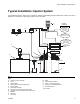
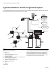
Typical Installation: Series Progressive System
The installation shown below is only a guide for selecting and installing system components. Contact your Graco dis-
tributor for assistance in planning a system to suit your needs.
Key:
A Lubricant output connection†
B Pump†
C Ignition switch*
D High-pressure lubricant supply lines*
E Primary metering device*
F Lubrication controller*
G Fill port (for reference only; non-tube-in-tube models only)
H Overflow port (for reference only)
J Breather (for reference only)
K Reservoir / Tank (for reference only)
L Secondary metering device
MMotor
N Bearing
*User provided
† The pump outlet requires modification to convert an Injector-based
system to Series Progressive system. Dyna-Star HF and HP Outlet
Adapter Kits 77X543 rated 4000 psi (275.8 bar, 27.58 MPa) and
77X544 rated 5000 psi (344.7 bar, 34.47 MPa) are available from
Graco. Contact Graco Customer Service or your local Graco distribu-
tor to identify the correct kit for your installation location.
FIG. 2
E
D
C
F
B
H
K
G
FrontBack
Low Reservoir
Level Switch
(Level Indicator,
optional)
Pressure Switch
for System Control
Remote Alarm Device
(Light or Horn)
(user provided
Controller
Capabilities
J
K
A
M
L
N
N
L
N
N
Motor Control
Board
Pump Power
Pump Signal