
User's Manual


Typical Installation: Injector System
332540E 5
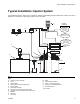
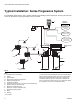
Typical Installation: Injector System
The installation shown in below is only a guide for selecting and installing system components. Contact your Graco
distributor for assistance in planning a system to suit your needs.
Key:
A Lubricant outlet connection
B Pump
C Ignition switch*
D High-pressure lubricant supply lines*
E Injector banks*
F Lubrication controller*
G Fill port (not used with Auto-Fill Shut Off)
H Overflow port (not used with Auto-Fill Shut Off)
J Breather
K Reservoir
L Vent Valve
M Motor
N Fluid overflow container
P Pump - remote filling station
R Reservoir - remote filling station
S Auto-Fill Shut Off
*User provided
FIG. 1
E
D
C
F
B
H
K
G
Front
Back
Low Reservoir
Level Switch
(Level Indicator,
optional)
Pressure Switch
for System Control
Remote Alarm Device
(Light or Horn)
(user provided
Controller
Capabilities
J
K
L
A
M
Motor Control
Board
Pump Power
Pump Signal
Vent Valve
N
P
R
S