Instructions, Repair and Parts Dyna-Star® HP Pump System 332540E EN Provides lubricant flow and pressure to operate a single line parallel automatic lubrication system. For automatic lubrication systems only. Not approved for use in European explosive atmosphere locations. Important Safety Instructions Read all warnings and instructions in this manual and the Dyna-Star HP and HF Pump instruction manual. Save all instructions. Maximum Working Pressure: 3500 psi (24.
Warnings Warnings The following warnings are for the setup, use, grounding, maintenance, and repair of this equipment. The exclamation point symbol alerts you to a general warning and the hazard symbols refer to procedure-specific risks. When these symbols appear in the body of this manual or on warning labels, refer back to these Warnings. Product-specific hazard symbols and warnings not covered in this section may appear throughout the body of this manual where applicable.
Warnings WARNING WARNING PRESSURIZED EQUIPMENT HAZARD Over-pressurization can result in equipment rupture and serious injury. • A pressure relief valve is required at each pump outlet. • Follow Pressure Relief Procedure in this manual before servicing. EQUIPMENT MISUSE HAZARD Misuse can cause death or serious injury. • Do not operate the unit when fatigued or under the influence of drugs or alcohol. • Do not exceed the maximum working pressure or temperature rating of the lowest rated system component.
Warnings WARNING WARNING BURN HAZARD Equipment surfaces and fluid that’s heated can become very hot during operation. To avoid severe burns: • Do not touch hot fluid or equipment. PERSONAL PROTECTIVE EQUIPMENT Wear appropriate protective equipment when in the work area to help prevent serious injury, including eye injury, hearing loss, inhalation of toxic fumes, and burns. This protective equipment includes but is not limited to: • Protective eyewear, and hearing protection.
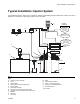
Typical Installation: Injector System Typical Installation: Injector System The installation shown in below is only a guide for selecting and installing system components. Contact your Graco distributor for assistance in planning a system to suit your needs.
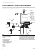
Typical Installation: Series Progressive System Typical Installation: Series Progressive System The installation shown below is only a guide for selecting and installing system components. Contact your Graco distributor for assistance in planning a system to suit your needs.
Installation Installation Pressure Relief Follow the Pressure Relief Procedure whenever you see this symbol. This equipment stays pressurized until pressure is manually relieved. To help prevent serious injury from pressurized fluid, such as skin injection, splashing fluid and moving parts, follow the Pressure Relief Procedure when you stop dispensing and before cleaning, checking, or servicing the equipment.
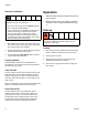
Operation Reservoir Installation HEAVY EQUIPMENT HAZARD Equipment is heavy. To avoid injury: • Be sure unit is securely mounted before operation. • Do not lift pressurized equipment. • Lifting or moving heavy equipment incorrectly can cause serious injury. To avoid serious injuries, such as muscle strain or back injuries, when moving pump always use a lifting aid secured to the pump lift ring. See Technical Data, in the pump instruction manual for pump weight. 1. Mount Reservoir on sturdy, flat surface.
Operation Filling Reservoir There are two reservoir filling options; Fill Port (G) or Auto-Fill Shut Off (S). Only one method of filling can be used. Filling Reservoir With Fill Port (G) NOTICE To prevent damage to the unit: Filling Reservoir With Auto-Fill Shut Off (S) Refer to Auto-Fill Shut Off Kit instruction manual 332518. Shutdown For normal system shut down, disconnect power by turning off the ignition switch (C). • Check Breather vent (J) for proper operation before filling reservoir.
Parts List Parts List Model 77X100: Dyna-Star Pump, 60#, Dip Stick, Reservoir, Cover, Vent Valve Model 77X101: Dyna-Star Pump, 90#, Dip Stick, Reservoir, Cover, Vent Valve Ref. No. 1 1a 1b 3 3a 3c 3d 3e 3f 3g 3h 3j 3k 3l 3m 3n 4 8 9 10 Part No.
Parts List Parts List Model 77X102: Dyna-Star Pump, 60#, Auto-Fill Shut Off, Reservoir, Cover, Vent Valve Model 77X103: Dyna-Star Pump, 90#, Auto-Fill Shut Off, Reservoir, Cover, Vent Valve Ref. No. 1 Part No.
Parts List Parts List Ref. No. Part No.
Technical Data Technical Data Maximum working pressure Pump wetted parts Vent valve wetted parts Reservoir wetted parts Reservoir overflow port size Reservoir fill port size Lubricant outlet port size Grease capacity Model 77X101, 77X103, 77X105 Model 77X100, 77X102, 77X104 Sound Data: All pumps 332540E 3500 psi (24.1 MPa, 241 bar See Dyna-Star HP and HF Pump manual: 332514 See Dyna-Star HP and HF Vent Valve Kit manual: 332519 steel, buna-n rubber 1/2 inch npt 1/2 inch npt 3/8 npt (f) 90 lb.
Dimensions Dimensions D E A F G B C 60 lb Models Ref US (inch) Metric (cm) US (inch) Metric (cm) A B C D E F 30.5 14.5 77.47 36.83 38.0 14.5 96.52 36.83 G 14 90 lb Models 1/2 inch npt 1/2 inch-14 npt 14.5 36.83 19.4 49.28 1/2 inch npt 1/2 inch-14 npt 14.5 36.83 27.0 36.
Notes Notes 332540E 15
Graco Standard Warranty Graco warrants all equipment referenced in this document which is manufactured by Graco and bearing its name to be free from defects in material and workmanship on the date of sale to the original purchaser for use. With the exception of any special, extended, or limited warranty published by Graco, Graco will, for a period of twelve months from the date of sale, repair or replace any part of the equipment determined by Graco to be defective.