
User's Manual


Installation
332518C 7
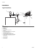
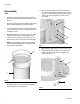
6. Install cover (e) over gasket (j) on reservoir (F) (FIG.
9).
7. Securely fasten cover (e) in place on top of reservoir
(F) using bolts (g) and nuts (gg) removed in Step 5,
page 5.
HINT: To ensure the cover is tightened correctly,
turn nuts (gg) until it is snug to reservoir. Then turn it
one more half turn.
NOTE: Do not over tighten cover (e) to reservoir (F).
Over tightening could crush the gasket (j) between the
cover and reservoir; pushing the gasket out of place and
breaking the seal.
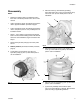
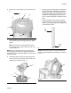
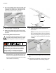
8. Install pump down-tube (p) through opening in the
center of the cover (e) and hole in the center of the
diaphragm (2) as shown in F
IG. 10.
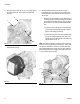
NOTE: The pump down tube has two parts (F
IG. 11):
• Fill tube (outer): directs grease to the bottom of
the pump during the fill operation. As grease is
filled into the reservoir, the diaphragm moves
up. When the grease level in the reservoir has
reached full, the diaphragm pushes the valve
pin up, closing off fluid path, ending the fill oper-
ation.
• Pump tube (inside): when pump is operating,
grease is drawn out of the bottom of the pump
reservoir, through the pump tube and dispensed
to the lubrication points.
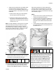
NOTE: When the pump (A) is correctly installed, the
breather (B) will be below the control box (r) as shown in
F
IG. 12.
FIG. 9
FIG. 10
e
g
j
F
gg
2
1
A
p
FIG. 11
FIG. 12
Fill
Tube
Pump
Tube
B
r