
User's Manual


Installation
6 332518C
Reassembly
NOTE:
• Reference numbers used in the following instruc-
tions refer to Kit Parts provided on the cover of this
manual.
• Upper case letters used in the following instructions
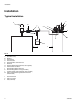
refer to Typical Installation provided on page 4.
• Lower case letters used in the following instructions
refer to component parts or user provided parts not
included in the Kit.
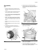
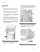
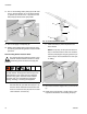
1. Align diaphragm (2) on reservoir (F) (F
IG. 6), match-
ing holes around the rim of diaphragm with the
holes in the top of the reservoir. Refer to F
IG. 6 to
determine the correct orientation of the diaphragm.
NOTE: The diaphragm (2) has six valves (not pic-
tured). When the diaphragm is correctly installed,
valves will face downward.
2. Install gasket (j) removed in step 6, page 5 over the
diaphragm (2) (F
IG. 6), matching holes in gasket
with the holes in rim of diaphragm.
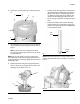
3. Remove screws (k) and nuts (kk) from accessory
cover plate (l) [installed on the pump reservoir cover
(e)] (F
IG. 7). Remove plate and gasket (m). Discard
screws, nuts, plate and gasket, you will not use
them again.
4. Align gasket (7) with holes (n) in cover (e) (F
IG. 8).
5. Install Auto-Fill Shut Off Valve (1) over gasket (7).
Install bolts (6) through holes (n). Tighten bolts
securely. See F
IG. 8.
FIG. 6
2
j
F
FIG. 7
FIG. 8
e
l
k
m
kk
1
6
n
e
7