Instructions Dyna-Star® HP and HF Pump Auto-Fill® Shut Off Kit 332518C EN Used with Dyna-Star HP or HF Pump to fill Graco Tank/Reservoir. For automatic grease lubrication systems only. Cannot be used with pumps equipped with a dip stick, low level indicator or follower plate. For professional use only. Important Safety Instructions Read all warnings and instructions in this manual and the Dyna-Star HP and HF Pump instruction manual. Save all instructions. 5000 psi (34.
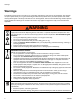
Warnings Warnings The following warnings are for the setup, use, grounding, maintenance, and repair of this equipment. The exclamation point symbol alerts you to a general warning and the hazard symbols refer to procedure-specific risks. When these symbols appear in the body of this manual or on warning labels, refer back to these Warnings. Product-specific hazard symbols and warnings not covered in this section may appear throughout the body of this manual where applicable.
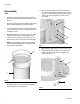
Auto-Fill Shut Off Overview Auto-Fill Shut Off Overview Pressure Relief Follow the Pressure Relief Procedure whenever you see this symbol. Reference letters used in the following instructions refer to Parts Table and Drawing shown on the cover of this manual. The Auto-Fill Shut Off is used for refilling the grease tank/reservoir in an automatic lubrication system. As grease is added to the reservoir, it pushes the diaphragm up to the top of the reservoir.
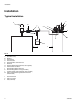
Installation Installation Typical Installation A K M L 1 3/4 E B G D C H J F FIG.
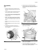
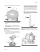
Installation Disassembly 4. Remove screws (c) and washers (d) holding Dyna-Star Pump (A) to cover (e) and remove pump from cover (FIG. 4). Save these parts to use for installation. NOTE: • Reference numbers used in the following instructions refer to Kit Parts provided on the cover of this manual. A c • Upper case letters used in the following instructions refer to Typical Installation provided on page 4.
Installation Reassembly NOTE: • Reference numbers used in the following instructions refer to Kit Parts provided on the cover of this manual. • Upper case letters used in the following instructions refer to Typical Installation provided on page 4. • Lower case letters used in the following instructions refer to component parts or user provided parts not included in the Kit. 3. Remove screws (k) and nuts (kk) from accessory cover plate (l) [installed on the pump reservoir cover (e)] (FIG. 7).
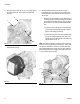
Installation 6. Install cover (e) over gasket (j) on reservoir (F) (FIG. 9). g • Fill tube (outer): directs grease to the bottom of the pump during the fill operation. As grease is filled into the reservoir, the diaphragm moves up. When the grease level in the reservoir has reached full, the diaphragm pushes the valve pin up, closing off fluid path, ending the fill operation.
Installation 9. Securely fasten pump (A) to cover (e) using screws (c) and washers (d). Use a wrench to tightened securely. 11. The Auto-Fill Shutoff Kit includes two supply hoses/tubes (3 or 4 as shown on the cover.) Only one hose/tube is used. Discard the hose/tube you do not use. A • Supply tube (4) (marked with the 16V750 aluminum tag) and two connector fittings (5) are used for manifold assemblies. Supply tube (3) can be discarded. It is not used for a manifold installation. c a.
Installation • Supply tube (3) (marked with the 16X381 aluminum tag) and two connector fittings (5), are used for vent valve assemblies. Supply tube (4) can be discarded. It is not used for a vent valve installation. sible location between the remote filling station pump (K) and the Auto-Fill Shut Off (1). This pressure relief valve is used to relieve pressure in the refill line and to reset the Auto-Fill Shut Off. See Typical Installation, page 4. a.
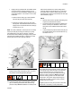
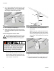
Installation 14. Turn on remote filling station pump (K) and fill reservoir (F) until the indicator pin on the Auto-Fill Valve (1) pushes up as shown in FIG. 18; pressure in the refill pump (K) builds and the pump stalls. bv G pin up dt 1 FIG. 18 15. Turn off air supply to refill pump (K). H FIG. 19: In line installation shown b. 16.
Installation Troubleshooting Problem Cause Solution 1. Disconnect refilling line. Refilling pump, stalls. Pressurized tank is not refilling. Auto-Fill Shut Off Valve is in closed condition and has not reset 2. Relieve all line pressure using the Remote Filling Station Pressure Relief procedure provided on page 10. Make sure valve pin is down. See Remote Filling Station Pressure Relief procedure, Step b, page 10.
Parts Parts Model 77X521 (FIG. 21) Ref 1 2 3 4 5 Part No. 16V582 16V748 16X381 16V750 121311 6 16X389 7 8 16V396 404157 Description Qty VALVE, auto shut off 1 DIAPHRAGM, assembly 1 TUBE, vent valve 1 TUBE, manifold 1 FITTING, connector, 3/8 in. npt* 2 x JIC BOLT, M8 x 1.25 x 2 mm (not 2 shown) SEAL, auto shutoff valve 1 CAP 1 8 5 1 5 4 3 7 *Prior to installation, apply thread sealant or PTFE Tape to all npt tapered pipe threads. 2 FIG. 21 Accessories Remote Electric Signaling (FIG.
Technical Data Technical Data . Auto-Fill Shutoff Valve for Dyna-Star HP or HF Pump US Maximum working pressure Inlet/Outlet Sizes Outlet (marked “0”) 5000 psi 3/8 in. npt(f) Inlet (refill - marked “1”) Maximum flow Wetted Parts Valve Seal Temperature Working temperature Metric 34.4 MPa, 344 bar 3/8 in. npt(f) 2 gpm 7.6 lpm neoprene rubber, zinc plated parts, stainless steel, chrome plated parts, plastic acetal fluorocarbon -13° F to +122°F -25°C to +50°C Dimensions 5.0 in. 12.7 cm 2.75 in. 6.
Graco Information To place an order, contact your Graco distributor or to identify the nearest distributor call, Toll Free: 1-800-533-9655, Fax: 612-378-3590 All written and visual data contained in this document reflects the latest product information available at the time of publication. Graco reserves the right to make changes at any time without notice. For patent information, see www.graco.com/patents. Original instructions. This manual contains English.