Instructions G3 Max Automatic Lubrication Pump 332305B EN For dispensing of NLGI Grades #000 to #2 greases and oil with at least 40cSt. For Professional Use Only. Not approved for use in explosive atmospheres or hazardous locations. Part Nos., page 3 5100 psi (35.1 MPa, 351.6 bar) Maximum Working Pressure Important Safety Instructions Read all warnings and instructions in this manual. Save these instructions. TI14705 Conforms to ANSI/UL 73 Certified to CAN/CSA Std. 22.
Contents Part / Model Numbers . . . . . . . . . . . . . . . . . . . . . . . 3 2 Liter Models . . . . . . . . . . . . . . . . . . . . . . . . . . . 3 4 Liter Models . . . . . . . . . . . . . . . . . . . . . . . . . . . 3 8 Liter Models . . . . . . . . . . . . . . . . . . . . . . . . . . . 4 12 Liter Models . . . . . . . . . . . . . . . . . . . . . . . . . . 4 16 Liter Models . . . . . . . . . . . . . . . . . . . . . . . . . . 4 Understanding the Model Number . . . . . . . . . . . 5 Warnings . . . . . . . . .
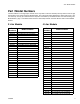
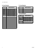
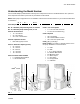
Part / Model Numbers Part / Model Numbers The Part Number is a six-digit unique number that is only used to order the G3 Pump. Directly related to this six digit Part Number is the configured Graco Model Number. This configured number identifies the distinct features of a specific G3 Pump. To help you understand each component that makes up the Model Number see Understanding Your Model Number, page 5. The tables below shows the relationship between each Part Number and its related Model Number.
Part / Model Numbers 8 Liter Models Part Numbers 4 Model Numbers 96G089 G3-G-24MX-8L0L00-10CV00R0 96G093 G3-G-ACMX-8L0L00-1D0V0000 96G097 G3-G-12MX-8L0L00-1DMVA2R3 96G100 G3-G-12MX-8L0L00-UDMVA1R2 96G104 G3-G-24MX-8L0L00-1DMVA2R3 96G109 96G112 G3-A-24MX-8L0L00-1DMVA2R3 96G119 G3-G-ACMX-8L0L00-1DMVA2R3 96G124 G3-A-ACMX-8L0L00-1DMVA2R3 96G127 G3-G-ACMX-8L0L00-UDMVA1R2 96G142 G3-G-12MX-8L0L00-10C00000 96G144 G3-G-24MX-8L0L00-10C00000 96G146 G3-G-ACMX-8L0L00-1D000000 96G152 G3-G-12M
Part / Model Numbers Understanding the Model Number Use the Code Sample provided below to identify each component’s location in the Model Number. The options for each component that make up the code are provided on the lists below. NOTE: Some pump configurations are not available. Contact Graco Customer Service or your local Graco distributor for assistance.
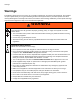
Warnings Warnings The following warnings are for the setup, use, grounding, maintenance, and repair of this equipment. The exclamation point symbol alerts you to a general warning and the hazard symbol refers to procedure-specific risk. When these symbols appear in the body of this manual, refer back to these warnings. Additional, product-specific warnings may be found throughout the body of this manual where applicable. WARNING ELECTRIC SHOCK HAZARD This equipment must be grounded.
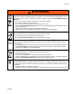
Warnings WARNING SKIN INJECTION HAZARD High-pressure fluid from dispensing device, hose leaks, or ruptured components will pierce skin. This may look like just a cut, but it is a serious injury that can result in amputation. Get immediate surgical treatment. • Do not point dispensing device at anyone or at any part of the body. • Do not put your hand over the fluid outlet. • Do not stop or deflect leaks with your hand, body, glove, or rag.
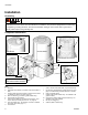
Installation Installation Grounding The equipment must be grounded. Grounding reduces the risk of electric shock by providing an escape wire for the electrical current in the event of malfunction or breakdown. This product is equipped with a cord having an equipment grounding conductor. The wire with insulation having an outer surface that is green with or without yellow stripes is the grounding wire.
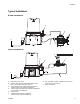
Installation Typical Installation Divider Installations B D E A F C Injector Installations E H F B D G A C A B C D E F Connected to fuse / power Pressure relief valve (Not included/required for each outlet - user supplied.
Installation Choosing an Installation Location AUTOMATIC SYSTEM ACTIVATION HAZARD Unexpected activation of the system could result in serious injury, including skin injection and amputation. This device has an automatic timer that activates the pump lubrication system when power is connected or when exiting the programming function. Before you install or remove the lubrication pump from the system, disconnect and isolate all power supplies and relieve all pressure.
Installation System Configuration and Wiring Fuses . Improper installation of the grounding conductor may result in a risk of electric shock. This product must be installed by a qualified electrician in compliance with all state and local codes and regulations. If the product is permanently connected: • it must be installed by a qualified electrician or serviceman. • it must be connected to a grounded, permanent wiring system.
Installation Alarm Output and Remote Illumination Response The following tables include graphical representations of the connector as it appears on the unit, a pin-out associated with the connector and a typical installation wiring diagram. An internal representative wiring diagram is included where it is deemed useful. Wire colors provided on these pages only refer to the power cable provided by Graco with this product.
Installation Wiring and Installation Diagrams The following Table identifies the wiring and installation diagrams provided in this manual.
Installation Power DIN AC - 15 foot: Part No. 16U790 Pin and Related Wire Color (FIG. 3) Pin Pin Name 1 2 3 4 Line NEUTRAL Not Used GROUND Color Black White Not Used Green Connector on Housing Connector on Cable (4) (4) (2) (1) (1) (2) (3) Example Wiring Diagram 1 2 3 4 FIG.
Installation Power DIN DC - 15 foot: Part No. 16U790 NOTICE Be sure when power is applied that stirring paddle rotates clockwise (when viewed from the top). If it is wired incorrectly paddle could rotate counter-clockwise which will damage the pump’s internal components. If this happens, stop the pump immediately and wire unit correctly. Pin and Related Wire Color (FIG.
Installation Power CPC DC -15 foot: Part No. 126217 Pin and Related Wire Color (FIG. 6) Pin Pin Name Color 1 2 3 4 5 6 7 Not Used -VDC +VDC Not Used Not Used Not Used Not Used Not Used Black White Not Used Not Used Not Used Green Connector on Housing Connector on Cable (2) (2) (3) (1) (3) (1) (7) (6) (4) (5) (4) (7) (5) (6) Example Wiring Diagram Ignition Switch Fuse 12V-pump - 7.5A - Graco kit #571039 24V pump - 4A - Graco kit #571040 1 2 3 4 5 6 7 FIG.
Installation Power CPC DC - 5 Wire Pin and Related Wire Color (FIG. 6) Part No.: 126218: 15 ft (4.5 m) Part No.: 126219: 20 ft (6.1 m) Part No.: 126220: 30 ft (9.1 m) NOTE: An Illuminated Remote Run Button Kit: 571030, 571031 for starting a manual run cycle if used in conjunction with a 5-wire CPC cable, is available from Graco. Contact your local Graco distributor or Graco Customer Service for additional information about these kits.
Installation Inputs (M12) See Technical Data, page 72 for ratings. Connector on Housing Pin-out (1) (4) 1 SW + 2 Not Used 3 SW - (2) 4 Signal (3) Example Wiring Diagram Dry Contacts 1 2 3 4 Sink (NPN) 2 or 3 wire 1 2 3 4 Source (PNP) 2 or 3 wire 1 2 3 4 FIG.
Installation Vent Valve Outputs See Technical Data, page 72 for ratings. Connector on Housing Pin-out (3) 1 Not Used 2 Relief+ 3 Relief (2) (1) Example Wiring Diagram 1 2 3 FIG.
Installation Alarm Outputs DC example shown. See Technical Data, page 72 for ratings. Connector on Housing Pin-out (1) 1 N.O. (3) 2 N.C. 3 COM 4 Not Used (4) (2) Example Wiring Diagram 1 A Fuse G3 Alarm +9-30V 1 Amp Max 1 2 3 4 Switch closes on alarm (shown in non-alarm position) FIG.
Installation Part No. 124333: Cable Pin Out (M12) Part No. 124300: Field Wireable Pin Out (M12) Wire Colors Item No. Color 1 2 3 4 Brown White Blue Black Wire Colors Item No. 1 2 3 4 Color Brown White Blue Black FIG. 11 FIG.
Installation Part No. 124594: 4 Pin Eurofast Field Wireable Connector Part No. 124595: 5 Pin Eurofast Field Wireable Connector FIG. 12 22 FIG.
Setup Setup Connecting to Auxiliary Fittings Pressure Relief Follow the Pressure Relief Procedure whenever you see this symbol. NOTICE Do not attach unsupported equipment to auxiliary fittings such as fill ports and pump element. Attaching unsupported equipment to these fitting can result in irreparable housing damage. This equipment stays pressurized until pressure is manually relieved.
Setup Setting Pump Outlet Volume 3. Tighten pump element fitting. Torque fitting to 50 in. lbs (5.6 N•m). NOTE: • Before making any adjustments to pump volume, Relieve Pressure following procedure on page 23. • Only use Graco supplied spacers to control output volume. • It may be necessary to repeat this outlet volume setup procedure after the pump is operating to re-adjust the volume of dispensed fluids. 1. Use a wrench to turn pump element counter-clockwise to loosen.
Setup Models without a follower plate: To start the pump press the manual run button. 1. Connect fill hose to inlet fitting (FIG. 16). E 3. Fill reservoir with grease until seal of follower plate breaches the vent hole (FIG. 18) and the majority of air is expelled from the reservoir. D vent hole FIG. 16 2. For higher viscosity fluids, start pump to rotate stirring paddle during fill to prevent air pockets from forming in grease. To start the pump press the manual run button. FIG.
Setup Filling Oil Unit • Only use oil appropriate for your application, automatic dispensing, and the equipment’s operating temperature. Consult with machine and lube manufacturer for details. • The reservoir can be filled using a hand operated pump, pneumatic pump or electric transfer pump. • Do not overfill (FIG. 19). • Do not operate G3 without reservoir attached. • Only use oils with viscosity at least 40 cSt. FIG. 20 a 2.
Quick Setup Guide Quick Setup Guide / ;<= /> ! " $$ ! %%" 8 ; "" ! &' * ' ,//8 : 8 :' ? & " / 8@ ' '8 B 8$ &/ ' 8 $ /&/ D $$ ! %%" 8 ; "" ! 332305B ;<= /> ! " &'
Max Model Setup Max Model Setup Control Panel Overview (FIG. 22) NOTE: Programming instructions begin on page 29. OFF TIME/BACKUP TIME DISPLAY • ON TIME/BACKUP TIME • LED lights when ON Time/Backup Time is running. Display shows time as MM:SS (minutes and seconds). i.e., 08:30 is 8 minutes: 30 seconds. Sets the limits for the amount of time to complete a cycle or build up pressure before a warning is activated. Counts down from a set time to zero.
Max Model Setup Programming the Max Model Powering Units With Controllers By default, units with controllers are set to operate in a timed mode with 1 minute of ON time and 8 hours of OFF time. The unit should be powered up in OFF mode, counting down from the 8 hours. If the unit powers up in ON mode and has not been primed, hold the reset button located on the control panel (example shown on the right) for 1 second to move to the OFF mode.
Max Model Setup Setting the Real Time Clock DMS ™ the list of months until the current month is displayed in the field. Equipped Models Only NOTE: Set the real time clock prior to plugging the USB flash drive into the pump. 2. Press the ENTER button to set the month. The 2-digit date displays indicating the G3 is now ready to program the date. Enter the Year: • • The year displays.
Max Model Setup • The LED next to C/P1 lights, indicating which sensor of the pump control you are programming using either a specific number of cycles or by monitoring a pressure switch. • C / P2 and C / P3 controls functions to the second and third sensors (when sensors are used). 1. Use the UP and DOWN ARROW buttons to move up and down through the numbers 0-2 until the desired number appears in the first hour (HH) field. • Only sensor inputs that are available on the unit can be programmed. 2.
Max Model Setup 4. The cycle field is a 2 digit number. When the correct first numeral of the number displays, press the ENTER button to save the number. The cursor automatically moves to the second number field. NOTE: A leading zero (0) must be entered in the first field if the number of cycles is fewer than 10. 5. Press the ENTER button, to save the C1 information.
Max Model Setup To determine the Backup Time, Graco recommends the user verify the length of time it takes to complete a typical cycle and double that value (to a maximum of 30 minutes). 6. After pressing the ENTER button to set the last SS field, all the programmed ON Time information is saved. The G3 automatically switches to the OFF Time SETUP MODE. Backup Time is setup after Cycle or Pressure Sensor Setup is complete.
Max Model Setup 2. Press the ENTER button to lock in the selection. The next MM number field to the right flashes indicating it is ready for programming. 3. Use the UP or DOWN ARROW button to scroll through numerals 0 to 9 until the desired number appears in the second MM number field. 4. Press the ENTER button to lock in the selection. The next number field to the right flashes and the LED lights under SS; indicating it is ready to program the seconds fields. 5.
Max Model Setup • • • An LED flashes under either HH when programming hours OR MM when programming minutes. 5. Repeat steps 1 - 4 to set the next MM (minutes) fields. OR In SETUP MODE the number displayed in the first field, on the left side of display blinks, indicating the device is ready to program the Backup Time hours. 6. After pressing the ENTER button to set the last MM field, the OFF Time information is saved. 7. After selecting ON, refer to page 32.
Max Model Setup 1. To set the OFF Time use the UP or DOWN ARROW button to scroll through numerals 0 to 9 until the desired number appears in the first HH (hour) field. 2. Press the ENTER button to lock in the selection. The next HH number field to the right flashes indicating it is ready for programming. 3. Use the UP or DOWN ARROW button to scroll through numerals 0 to 9 until the desired number appears in the second HH number field. 4. Press the ENTER button to lock in the selection.
Max Model Setup flashes and the LED lights under SS; indicating it is ready to program the seconds fields. 5. Repeat steps 1 - 4 to set the SS (seconds) fields. 6. After pressing the ENTER button to set the last SS field the G3 automatically switches to the RUN MODE. DMS ™ Models Only Downloading Data 1. Plug the USB flash drive into the USB port. NOTE: The G3 pump stops pumping as soon as the USB flash drive is plugged into it. 2. The system automatically begins downloading data to the USB drive. 3.
Max Model Setup 9. G3 pump restarts cycle in the OFF mode. 10. Remove the USB flash drive. 11. After the USB flash drive is removed, press and hold the UP and DOWN ARROW buttons for 3 seconds to enter the SETUP MODE (see Entering Setup Mode, page 29). 12. In SETUP MODE, set the YEAR, MONTH, DATE and TIME (see Setting the Real Time Clock, page 30). 13. After pressing the ENTER button to set the TIME, press the RESET button to exit the SETUP MODE. Viewing the UNIT DMS ID Number 1.
Operation / Data Log Operation / Data Log During operation the G3 Pump stores information as Log and Summary Files. Logs contain the following information: • Log Name • DMS ID Number • Current Software Graco Part Number • Current Software Version • Date and Time of Upload System Event Log The System Event Log lists the date and time of the last 800 common system events such as pump cycles, manual run and setting changes. The most recent event is listed first.
Operation / Data Log Example Event Log 2: Pump cycle of an injector valve system with a pressure switch feedback. Date 9/29/2010 9/29/2010 9/29/2010 9/29/2010 9/29/2010 Time 13:28:12 13:23:12 13:23:11 13:23:11 13:22:20 Description Venting Completed Venting Detected Pump Run Off P1 Pressure Completed Pump Run On Venting Detected In an injector system, the pump on cycle has completed and the system is currently venting pressure through the vent valve.
Operation / Data Log Common Error Log entries are listed below. Software Fault An internal software error occurred. Contact Graco Customer Service. Low Level Warning The unit entered a low level warning mode and is running low on material. The pump continues to dispense material for the duration of the low level alarm time specified by the unit. Low Level Fault The alarm time in low level warning has elapsed. The unit will not pump until the reservoir is filled and the fault is cleared.
Operation / Data Log Functional Summary The Functional Summary contains two types of data. • The first report type, labeled User under the Type heading in the first column of the Sample Functional Summary, only provides data compiled since the last time the Functional Summary was reset through present day (see A6 - Clearing the Functional and Technical User Summary, page 49).
Operation / Data Log Common Functional Summary Data entries are listed below. Number of Cycles The number of lubrication cycles the unit has started. Total Run Hours Total amount of hours the pump has been in the ON mode of the ON/OFF cycle. Total Powered On Hours Total number of hours that the unit has been powered on. Local Manual Run The number of times the manual run button was pressed. Remote Manual Run The number of times the remote manual run button was pressed.
Operation / Data Log Technical Summary The Technical Summary contains two types of data. • The first report only provides data compiled since the Pump Summary was reset to present day (see A6 - Clearing the Functional and Technical User Summary). Common Technical Summary Data entries are listed below. Average Input Board Voltage (DC) The average input voltage measured by the internal circuit board. Peak Input Board Voltage (DC) The peak input voltage measured by the internal circuit board.
Advanced Programming Advanced Programming There are 7 Advanced Programming options. The following Table Identifies each option and when it is used. Advanced Option Model A1 Max A2 Max A3 Max A4 Max A5 Max Setting Format/ Description Why Use This? Lockout Code (Optional) Low Level Alarm Time Secures setup modes with PIN Prevents unauthorized users to adjusting settings.
Advanced Programming Entering a PIN Code for the First Time A1 - Setting Up PIN Code A PIN Code can be programmed into the G3 to protect the settings from inadvertently being changed by unauthorized users. 1. The cursor is automatically positioned to enter the first character of the PIN Code. Use the UP and DOWN ARROW buttons to move up and down through the numbers 0-9 until the first number in the PIN code is displayed in the field. 1. Press the UP ARROW button for 10 seconds. 2.
Advanced Programming A2 - Low Level Alarm Time Pump ON mode only. Programs the amount of time in MM: SS (minutes and seconds) the pump can run between a Low Level Warning and a Low Level Fault to help protect unit from running dry. The maximum recommended length of time is 3:00 minutes. Fault, and Low Level LED illuminate. (Max Model Display shown in illustration below). 3. Use the UP or DOWN ARROW button to scroll through numerals 0 to 9 until the desired number appears in the second MM number field. 4.
Advanced Programming To set Vent Valve Time: NOTE: • The LED next to the clock in the OFF field lights and P1, P2, and P3, indicating the Vent Valve Time is being programmed. 7. After pressing the ENTER button to set the last seconds field, all the programmed Time information is saved. Unit exits Advanced Programming. A-4 Alarm Retry • Time is set as minutes and seconds (MM:SS) only. • The small flashing LED under the MM indicates you are setting Minutes.
Advanced Programming 3. When the correct number displays, press the ENTER button to set the number. 4. Repeat 2 - 3 to set the remaining fields. 5. Press the ENTER button to exit Advanced Programming. 3. Press the ENTER button to exit Advanced Programming. A6 - Clearing the Functional and Technical User Summary (DMS™ Models only) The Pump Summary shows run details since the last time the summary was cleared. A-5 Active Alarm Changes the alarm output behavior.
Advanced Programming A-7- Constant Alarm Output on Fault This function changes the behavior of the alarm output in a fault from either toggling once every second (default) or steady on. Fault and Warning LEDs Illuminate HH MM SS ## ON OFF MM : SS HH : MM ! C P1 C P2 C C P3 P 123 FIG. 27 1. The default OFF is displayed. The alarm output will toggle once a second. 2. Press the UP or DOWN ARROW to change OFF to ON on the display to change the alarm output to be on steady 3.
Run Mode Run Mode • Time Control After setup is complete, the G3 automatically begins to run the OFF Time sequence (FIG. 28). • When the OFF Time count reaches zero, the G3 Automatic Lubrication Pump turns the pump on and it runs for the programmed ON Time cycle (FIG. 29). (Notice the ON Time LED is now illuminated on the display.) • The G3 runs the programmed OFF sequence. The example shown in FIG. 29 shows an ON Time of 8 minutes and 42 seconds before the lubrication cycle ends.
Run Mode Lubrication Mode (Pump ON) Controls In Max models the Lubrication Mode (Pump ON) can be controlled by either cycle and/or pressure sensors. If cycle and/or pressure controls have been set to something other than OFF the display will alternate between cycles (C1, C2, C3) and/or active sensors (P1, P2, P3) and Backup Time. Pressure Control • A single triggered count in a pressure based system (P1). Typically a pressure switch on the end of a line of injectors.
Run Mode Backup Time HH MM SS ## ON OFF MM : SS HH : MM ! • In both Cycle and Pressure modes a Backup Time (maximum run time) has been set. • The LED(s) next to all programmed sensors (C/P1, C/P2, C/P3) illuminate. • The display shows time remaining until a fault. The example shown in FIG. 33 shows 14 minutes and 33 seconds left until the fault occurs.
Run Mode With machine count set, the Rest Cycle (Pump OFF) is ended when the machine count reaches zero (0000). Machine Count Backup Time In Machine Count mode, if a Backup Time (maximum rest time) has been set: • A set number of triggered counts. • The LED next to 1-2-3 illuminates (FIG. 35). • The LED next to 1-2-3 illuminates (FIG. 34). • • The display indicates the number of machine counts remaining. The display shows the amount of time remaining till a fault. The example shown in FIG.
Run Mode Additional Controls Prelube Venting The Prelube function has been selected. Prelube delay is set to 00:00: In Max models a Vent Time can be set using the Advanced Programming mode (page 47). This is typically done in a Pressure Based System (P1) to allow injectors to reset. • Power to the unit cycles OFF then ON. • Unit immediately begins a lubrication cycle. • Max Model - display shows Cycle/Pressure/Backup Time (See Max Model Lubrication Mode Controls, page 52).
Run Mode Manual Run Cycle To run an extra (non-programmed) lubrication cycle, push the Manual Start button. NOTE: Manual Run option is not available while unit is in Vent Mode.
Alarms Alarms Any time a Fault / Warning occurs, a combination of LED’s will illuminate to notify you there is a problem and help identify the kind of Fault / Warning has occurred. • Faults and Warnings will not automatically clear. • To clear an fault, press and hold the RESET button on the display button pad for 3 seconds. • To clear a warning press and immediately release the RESET button. Fault / Warning Scenarios The following pages describe the most likely fault / warnings you could receive.
Alarms Low Level Fault HH MM SS ## ON OFF MM : SS HH : MM ! C P1 Cycle / Pressure Warning C P2 C C P3 P HH 123 MM SS ## ON OFF MM : SS HH : MM C P1 58 C P2 C C P3 P 123 ! Add lubricant to reservoir. Level of lubricant in reservoir is low and additional lubricant needs to be After lubricant is added. added press and hold the Unit stops pumping and displays amount of accu- RESET button to clear fault. mulated time since the alarm was triggered.
Alarms Cycle / Pressure Fault HH MM SS ## ON OFF MM : SS HH : MM ! In cycle mode indicates that a cycle was not completed in the user-defined amount of time. C P1 C P2 C C P3 P Examine system to determine if you have a plugged or broken line or other component failure, i.e., divider valve, injector. Press and hold the RESET button to clear fault. 123 LED corresponding to the affected sensor input blinks.
Alarms System Fault HH MM SS ## ON OFF MM : SS HH : MM An internal fault has occurred. Contact Graco Customer Service. The measured motor current is above the recommended operating maximum value. Continued use at excessive motor currents could reduce life or cause permanent damage. Examine system to make sure it is operating correctly.
Alarms Temperature Warning HH MM SS ## ON OFF MM : SS HH : MM ! C P1 C P2 C C P3 P 123 USB Error HH The internal temperature of Ensure the unit is used in the unit is out of its recom- the correct operating envimended operating range. ronment for the specific temperature: -13° F to Use of the unit outside of 158° F (-25° C to 70°C). the recommended temperature range could cause If necessary contact Graco Customer Service. degraded system performance and possible damage.
Troubleshooting Troubleshooting Problem Unit does not power on Cause Incorrect/loose wiring Tripped external fuse due to internal component failure Solution Refer to Installation instructions, page 8. Contact Graco Customer Service. Unit does not power on (DC models only) Tripped external fuse due to pumping Replace lubricant with pumpable non-cold weather lubricant in cold lubricant, rated for environmental weather -13°F (-25°C) conditions and application.
Troubleshooting Problem Cause In an Injector System without sensor Vent valve time needs to be configfeedback, unit does not vent properly ured Solution Refer to Advanced Programming to set ON Time, page 45. Display acts erratically Faulty cycle/pressure wiring connec- Unplug cycle/pressure cables from tion to unit G3. Plug cables in one at a time to identify the faulty connection.
Maintenance Maintenance Frequency Component Required Maintenance Daily and at refill Zerk Fittings Keep all fittings clean using a clean dry cloth. Dirt and/or debris can damage pump and/or lubrication system. Daily G3 Pump Unit and Reservoir Keep pump unit and reservoir clean using a clean dry cloth. Daily Display Keep display clean using a clean dry cloth. Monthly External Wiring Harness Verify external harnesses are secure.
Parts - 2 Liter Models Parts - 2 Liter Models 40b Follower Plate Models Only Low Level Grease Models Only 43 45 40a 44 35 42 57 27 1 41 60 16 36 15 23 13 14 Low Level Oil Models Only 18 12 3 37 67 1 21 31 66 33 34 17 3 3 30 4 2 1 Torque to 4 in. lbs (0.45 N.m) 2 Torque to 30 in. lbs (3.4 N.m) 3 Torque to 50 in. lbs (5.6 N.
Parts - 4 Liter and Larger Models Parts - 4 Liter and Larger Models Follower Plate Models Only 40b 40a 43 44 Low Level Grease Models Only 41 45 36 42 35 57 61 27 1 60 16 13 62 23 14 15 12 18 31 Low Level Oil Models Only 3 37 21 1 67 33 34 17 3 4 2 30 3 66 1 Torque to 4 in. lbs (0.45 N.m) 2 Torque to 30 in. lbs (3.4 N.m) 3 Torque to 50 in. lbs (5.6 N.
Parts Parts Ref Part 1 Description BASE, three pump housing Qty 1 3 278142 COVER, bottom, with seal 1 4 115477 SCREW, mach, torx pan hd 9 12 127079 13 RECT-RING, included in Kit 571042, 571069, 571179 O-RING, 258, included in Kit 124396 571042, 571044, 571045, 571069, 571179 1 2 14 PLATE, ricer 1 15 BEARING, ball 1 16 PADDLE, stirring, 2 Liter models without follower plate - models 96G017, 96G019, 96G021, 96G023, 96G025, 96G030-96G032, 96G035-96G037, 96G098, 96G110, 96G125, 96G178, i
Parts Ref 30 ‡ Part Description BOARD, circuit, Max, models 96G017-96G021, 96G023-96G026, 96G030-96G032, 96G035-96G037, 96G088-96G090, 96G092-96G094, 96G096, 96G097, 96G103-96G109, 96G113, 258697 96G118-96G124, 96G128, 96G141-96G146, 96G151, 96G152, 96G155, 96G156, 96G159, 196G160, 96G164, 96G166, 96G168, 96G177, 96G178, 96G181, 96G183 BOARD, circuit, Max, DMS™ models 96G098-96G100, 96G110-96G112, 96G115, 96G116, 96G125-96G127, ‡ 262463 96G132, 96G133, 96G153, 96G154,96G157, 96G158, 96G161, 96G162,
Parts Ref Part Description RESERVOIR, 8 liter, grease, 96G089, 96G093, 96G097, 96G100, 96G104, 96G112, 96G119, 96G127, 96G142, 40a 96G144, 96G146, 96G152, 96G154, 96G156, 96G158, 96G177 RESERVOIR, 8 liter, oil, 96G109, 40b 96G124, 96G176, 96G186, included in Kit 571182 RESERVOIR, 12 liter, 96G105, 40a 96G120, 96G164, 96G165 RESERVOIR, 16 liter, 96G106, 40a 96G121, 96G166, 96G168, 96G169, 96G185 SEAL, follower plate, 2 liter models 278139 96G018, 96G020, 96G024, 96G026, 96G115, 96G132 41 SEAL, follower p
Parts Ref 60 61 62 66 67 Part Description WASHER, low level, models 96G017-96G021, 96G023-96G026, 96G030-96G032, 96G035-96G037, 96G088-96G090, 96G092-96G094, 96G096-96G100, 96G103-96G106, 96G110-96G113, 96G115, 16D984 96G116, 96G118-96G121, 96G125-96G128, 96G132, 96G133, 96G141-96G146, 96G151-96G162, 96G164, 96G165-96G168, 96G177, 96G178, 96G181, 96G183, 96G185 RESERVOIR, mid-section, 8 liter models 96G089, 96G093, 96G097, 96G100, 96G104, 96G109, 96G112, 96G119, 96G124, 96G127, 96G142, 96G144, 96G1
Parts Pressure Relief Valves Fuses Important Information regarding Pressure Relief Valve 16C807. Part Pressure Relief Valve 16C807 can only be used on the G3 Pump. It is not intended for use with any other products. The pressure relief valve uses a pressure adjustment screw (a) to set the pressure release point. It is not intended as a way to relieve pressure during normal operation, but as a protective measure in the event there is an unintended pressure increase in the system.
Technical Data Technical Data A Maximum Working Pressure Power 100-240 VAC 12 VDC 24 VDC Outputs - Alarm Relay Rated Load Max Operation Voltage Max Operating Current Max Switching Capacity Min Permissible Load Outputs - Vent Valve Required Vent Valve Type Output Voltage 100/240 VAC 12 VDC 24 VDC Max Operating Current Max Operating Power Inputs - Cycle Pressure, 1, 2, 3, Machine Count Required Switch Type Sensor Voltage 100/240 VAC 12 VDC 24 VDC Load Current 100/240 VAC 12 VDC 24 VDC Maximum Residual Volt
Technical Data Fluid Grease Models Oil Models Pumps Pump Output Pump Outlet Reservoir Size IP Rating Sensor Inputs Ambient Temps Weight (Dry - includes power cord and plug) Without follower plate With follower plate Wetted Parts Sound Data Grease NLGI 000 - #2 At least 40 cSt oil. Up to 3 0.12 in.3 (2 cm3) / minute per outlet - 2 spacers 0.18 in.3 (3 cm3) / minute per outlet - 1 spacer 0.25 in.3 (4 cm3) / minute per outlet - 0 spacers 1/4-18 NPSF.
Technical Data Mounting Pattern (For correct mounting configuration, choose either Option 1 or Option 2). See P/N 126916 template. Option 1 0.367inch 9.3 mm 7.087 inch 180.0 mm 2x Ø 0.366 inch 9.3 mm 1.180 inch 30.0 mm 3.268 inch 83.0 mm 3.544 inch 90.0 mm Option 2 0.722 inch 18.3 mm 6.378 inch 162.0 mm 2x Ø 0.366 inch 9.3 mm 0.708 inch 18.0 mm 3.740 inch 95.0 mm 3.189 inch 81.0 mm FIG.
Notes Notes 332305B 75
Graco Standard Warranty Graco warrants all equipment referenced in this document which is manufactured by Graco and bearing its name to be free from defects in material and workmanship on the date of sale to the original purchaser for use. With the exception of any special, extended, or limited warranty published by Graco, Graco will, for a period of twelve months from the date of sale, repair or replace any part of the equipment determined by Graco to be defective.