
User's Manual


Component Identification
6 313877E
Component Identification
Control Boxes
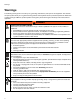
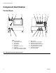
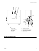
FIG. 1: Micrometer and LRT PD44 Control Box
7
2
5 34
6
1
7
2
5 34
6
1
7
2
5 34
6
1
12
56
3
7
12
9
13
10
14
11 8
4
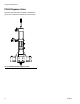
SIGNAL CONNECTION
PG-3
A TANK
LEVEL CONTROLS
PG-4
B TANK
LEVEL CONTROLS
PG-2
CUSTOMER I/O
100V TO 250V AC
PG-8
START
MACHINE I/O
PG-1
1
3
4
2
EXT
LOAD
DISP
RET
106
VALV E
108 107
SPOOL
105
CYLINDER
AIR
D
Key:
A Emergency Stop
B Control Power Switch
C Touch Panel
D Alarm Speaker
E Power Input
F Start Options Connection
GCustom I/O
H A Tank Level Controls Connection
J B Tank Level Controls Connection
KMain Air Inlet
L Dispense Valve I/O Connection
M Spool Valve Load Connection
N Spool Valve Dispense Connection
P Air Cylinder Extend Connection
R Air Cylinder Retract Connection
S Air Pressure Regulator
T Air Pressure Gauge
ST
AB C
HJGFE
KM NPR
L