
User's Manual


Setup
10 313877E
Setup
Micrometer and LRT PD44 Only
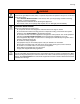
1. Connect air supply to main air inlet on control box.
Air supply must include a shut-off/bleed valve that
bleeds pressure past the shut-off/bleed valve and an
air-water separator/filter.
2. Connect air lines from control box to dispense valve.
Match the number and color codes on the fittings
and connections. See the following table and illus-
tration.
3. Connect Dispense Valve I/O, and Start Options
logic cables. If level controls are installed, connect
Level Controls logic cables.
4. Adjust air pressure regulator to 80 psi (0.6 MPa,
6bar).
5. Perform Setup procedure for dispense valve and
feed system components. See Related Manuals on
page 3.
Connection
Color
Connection
Description
Red Extend
Blue Retract
Yellow Dispense
Green Reload
7
2
5 34
6
1
7
2
5 34
6
1
7
2
5 34
6
1
12
56
3
7
12
9
13
10
14
11 8
4
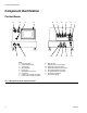
SIGNAL CONNECTION
PG-3
A TANK
LEVEL CONTROLS
PG-4
B TANK
LEVEL CONTROLS
PG-2
CUSTOMER I/O
100V TO 250V AC
PG-8
START
MACHINE I/O
PG-1
1
3
4
2
EXT
LOAD
DISP
RET
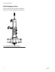
106
VALV E
108 107
SPOOL
105
CYLINDER
AIR
7
2
5 34
6
1
7
2
5 34
6
1
7
2
5 34
6
1
12
56
3
7
12
9
13
10
14
11 8
4
SIGNAL CONNECTION
PG-3
A TANK
LEVEL CONTROLS
PG-4
B TANK
LEVEL CONTROLS
PG-2
CUSTOMER I/O
100V TO 250V AC
PG-8
START
MACHINE I/O
PG-1
1
3
4
2
EXT
LOAD
DISP
RET
106
VALV E
108 107
SPOOL
105
CYLINDER
AIR
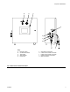
NOTICE
Feed system and main logic control system must
use separate air supplies.
7
2
5 34
6
1
7
2
5 34
6
1
7
2
5 34
6
1
12
56
3
7
12
9
13
10
14
11 8
4
SIGNAL CONNECTION
PG-3
A TANK
LEVEL CONTROLS
PG-4
B TANK
LEVEL CONTROLS
PG-2
CUSTOMER I/O
100V TO 250V AC
PG-8
START
MACHINE I/O
PG-1
1
3
4
2
EXT
LOAD
DISP
RET
106
VALV E
108 107
SPOOL
105
CYLINDER
AIR