
User's Manual


Setup
22 313876F
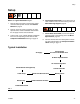
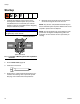
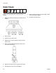
Tank Level Sensor Wiring
Schematic
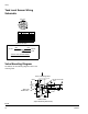
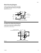
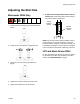
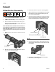
Valve Mounting Diagram
As desired, use the following diagram to mount the
metering valve.
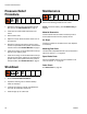
TYPICAL LEVEL SENSOR WIRING
BLU
BLK
7
NUMBER
PIN USAGE
4
5
6
2
3
PIN
1
TANK LEVEL
12
345
67
BROWN
BLACK
BLUE
BROWN
BLACK
BLUE
BLUE
24 VDC+
BRN
COM
SIGNAL
HIGH
LOW
LOW
LOW
LOW
HIGH
HIGH
USAGE
JUMPER PIN 6 AND 7
FIG. 8
1.63
3.75
3.25
0.563
4X Ø 0.188
DOWEL PINS
0.862
0.190
1.75
L
1.50
0.75
C
1.06
0.38
4X 10-24 X 0.5 DP
Bottom View
Front of Metering Valve
(Spool Assembly Not Shown)