Operation - Maintenance PD44 313876F ENG Metering Valves and Feed Systems Meter, mix, and dispense system for precise two-component micro-dispensing of sealants and adhesives. Not approved for use in European explosive atmosphere locations. Important Safety Instructions Read all warnings and instructions in this manual. Save these instructions. See page 3 for model information, including maximum working pressure and approvals. See page 6 for product configuration information.
Contents Related Manuals . . . . . . . . . . . . . . . . . . . . . . . . . . . 3 Models . . . . . . . . . . . . . . . . . . . . . . . . . . . . . . . . . . . 3 Warnings . . . . . . . . . . . . . . . . . . . . . . . . . . . . . . . . . 4 Product Configurator . . . . . . . . . . . . . . . . . . . . . . . 6 Accessories . . . . . . . . . . . . . . . . . . . . . . . . . . . . . . 11 Isocyanate Conditions . . . . . . . . . . . . . . . . . . . . . 13 Material Self-ignition . . . . . . . . . . . . . . . . . . . . .
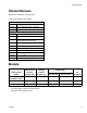
Related Manuals Related Manuals Manuals are available at www.graco.com Component manuals in U.S. English.
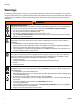
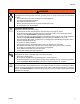
Warnings Warnings The following warnings are for the setup, use, grounding, maintenance, and repair of this equipment. The exclamation point symbol alerts you to a general warning and the hazard symbol refers to procedure-specific risk. Refer back to these warnings. Additional, product-specific warnings may be found throughout the body of this manual where applicable. WARNING SKIN INJECTION HAZARD High-pressure fluid from gun, hose leaks, or ruptured components will pierce skin.
Warnings WARNING ELECTRIC SHOCK HAZARD This equipment must be grounded. Improper grounding, setup, or usage of the system can cause electric shock. • Turn off and disconnect power cord before servicing equipment. • Use only grounded electrical outlets. • Use only 3-wire extension cords. • Ensure ground prongs are intact on power and extension cords. • Do not expose to rain. Store indoors. EQUIPMENT MISUSE HAZARD Misuse can cause death or serious injury.
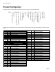
Product Configurator Product Configurator This system can be ordered with many different options as shown in the configurator below.
Product Configurator Code E Part Low Volume Rod Material NOTE: See code FG for last two digits of part number A 9641__ Hardened Steel B 9642__ Stainless Steel, UHMW C 9643__ Tungsten Carbide, UHMW Code FG Part Low Volume Rod Size NOTE: See code E for first four digits of part number 01 ____01 1.25 mm rod diameter 02 ____02 1.38 mm rod diameter 03 ____03 1.50 mm rod diameter 04 ____04 1.63 mm rod diameter 05 ____05 1.75 mm rod diameter 06 ____06 2.00 mm rod diameter 07 ____07 2.
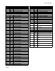
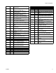
Product Configurator Code L 1 2 3 4 5 6 7 8 9 A B C 8 Part Controls 964035 Pneumatic, micrometer, wire harness only 964036 Pneumatic, micrometer, HMI controls, low level 964037 Pneumatic, micrometer, HMI controls, low level, I/O package 964038 Pneumatic, micrometer, HMI controls, low level, high level 964039 Pneumatic, micrometer, HMI controls, low level, high level, I/O package 964040 Pneumatic, linear resistive transducer, wire harness only 964041 Pneumatic, linear resistive transducer, HMI controls
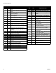
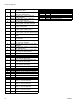
Product Configurator 19 20 21 22 23 24 25 26 27 28 29 30 31 32 NN Code P 1 3 5 N 964068 5 gallon tank, support, 5:1 pump, agitator, stainless steel 964069 5 gallon tank, support, 5:1 pump, agitator, vacuum fill, stainless steel 964070 10 gallon tank, support, diaphragm pump, mild steel 964071 10 gallon tank, support, diaphragm pump, agitator, mild steel 964072 10 gallon tank, support, diaphragm pump, agitator, vacuum fill, mild steel 964073 10 gallon tank, support, diaphragm pump, stainless steel 964074 1
Product Configurator 19 20 21 22 23 24 25 26 27 28 29 30 31 32 NN Code T 1 3 5 7 964068 5 gallon tank, support, 5:11 pump, agitator, stainless steel 964069 5 gallon tank, support, 5:1 pump, agitator, vacuum fill, stainless steel 964070 10 gallon tank, support, diaphragm pump, mild steel 964071 10 gallon tank, support, diaphragm pump, agitator, mild steel 964072 10 gallon tank, support, diaphragm pump, agitator, vacuum fill, mild steel 964073 10 gallon tank, support, diaphragm pump, stainless steel 964074
Accessories Accessories Mixer Kits with Shroud Part Description 964034 Mixer, Kit, 3/16 in. (4.8mm) x 24, 10 taper tip mixers with shroud 964032 Mixer, Kit, 3/16 in. (4.8mm) x 32, 10 taper tip mixers with shroud 964028 Mixer, Kit, 3/16 in. (4.8mm) x 32, 10 Luer Lock tip mixers with shroud/sleeve 964033 Mixer, Kit, 1/4 in. (6.5mm) x 24, 10 taper tip mixers with shroud 964029 Mixer, Kit, 1/4 in. (6.5mm) x 24, 10 Luer Lock tip mixers with shroud/sleeve 964030 Mixer, Kit, 1/4 in. (6.
Accessories O-Rings and Seals Part Description Part Description 24E247 Kit, O-ring, chemical resistant, PD44 16B286 Seal, Posipack, 4.50, ZAP 24E248 Kit, Seal, Spool, H.V., PD44 16B287 Seal, Posipack, 4.63, ZAP 24E249 Kit, Seal, Spool, L.V., PD44 16B288 Seal, Posipack, 4.75, ZAP 16B265 Seal, Posipack, 1.25, ZAP 16B289 Seal, Posipack, 4.88, ZAP 16B266 Seal, Posipack, 1.38, ZAP 16B290 Seal, Posipack, 5.00, ZAP 16B267 Seal, Posipack, 1.50, ZAP 16B291 Seal, Posipack, 5.
Isocyanate Conditions Isocyanate Conditions To prevent exposing ISO to moisture: • Spraying or dispensing materials containing isocyanates creates potentially harmful mists, vapors, and atomized particulates. • Read material manufacturer’s warnings and material MSDS to know specific hazards and precautions related to isocyanates. • Prevent inhalation of isocyanate mists, vapors, and atomized particulates by providing sufficient ventilation in the work area.
Grounding Grounding This product must be grounded. In the event of an electrical short circuit, grounding reduces the risk of electric shock by providing an escape wire for the electric current. Metering valve: attach ground wire from grounding lug to true earth ground. See Component Identification starting on page 15. Fluid hoses: use only electrically conductive hoses. Feed system components: attach ground wire from grounding lug to true earth ground. See feed system manual for grounding points.
Component Identification Component Identification Typical System Configurations Base Unit 0 1 2 3 4 5 6 7 8 9 0 B Side Feed 1 A Side Feed Controls WARNING Do Not service without removing air pressure and waring saftey glasses. Liquid Control Corp. 8400 PORT JACKSON AVE. N.W. NORTH CANTON, OH 44720 USA SERIAL NUMBER MODEL NUMBER TO SH CK TO E PU LO LL AS PU LE RE B Side Feed A Side Feed Base Unit Controls CONTROL POWER Liquid Control Corp. 8400 PORT JACKSON AVE. N.W.
Component Identification Typical Feed System Components 5 Gallon Pail Cover with Diaphragm Pump 5 Gallon Pail Cover with Diaphragm Pump and Agitator 20 oz Cartridge Feed with Mounting Post 1 Gallon Ram and Pump F WARNING 0 psi 20 0 DO NOT SERVICE WITHOUT REMOVING AIR PRESSURE AND WEARING SAFETY GLASSES. 5 Gallon Pail Cover with 5:1 Transfer Pump 5 Gallon Pail Cover with Diaphragm Pump 5 Gallon Ram and 11:1 Transfer Pump FIG.
Component Identification Typical Feed System Components (continued) R 5 Gallon Tank with Diaphragm Pump and Stand 5 Gallon Tank with 5:1 Pump and Stand 15 12 8 4 0 8 4 30 0 19 26 26 psi 30 19 22 psi 22 15 12 R 10 Gallon Tank with Diaphragm Pump, Agitator, Vacuum, and Stand 10 Gallon Tank with 5:1 Pump, Agitator, Vacuum, and Stand FIG.
Component Identification Micrometer PD44 Metering Valve T G S L H P M N E C F R R K J A D B D Side View Front View Key: A B C D E F G H J K A Material Inlet B Material Inlet Grounding Lug Spool Assemblies Metering Rods Oil Cup Retaining Block Extend Air Inlet Retract Air Inlet Dispense Air Inlet Reload Air Inlet L M N P R S T Extend Air Flow Adjustment Knob Retract Air Flow Adjustment Knob Retract Proximity Switch Extend Proximity Switch Spool Valve Proximity Switch Shot Size Locking Ri
Component Identification LRT PD44 Metering Valve U L G H M E F C R R K J D B A D Front View Side View Key: A B C D E F G H J A Material Inlet B Material Inlet Grounding Lug Spool Assemblies Metering Rods Oil Cup Retaining Block Extend Air Inlet Retract Air Inlet Dispense Air Inlet K L M R U Reload Air Inlet Extend Air Flow Adjustment Knob Retract Air Flow Adjustment Knob Spool Valve Proximity Switch Transducer Connection FIG.
Component Identification Motor Driven PD44 Metering Valve W V X W E C P F N R R K J D B A D Side View Front View Key: A B C D E F J K L A Material Inlet B Material Inlet Grounding Lug Spool Assemblies Metering Rods Oil Cup Retaining Block Dispense Air Inlet Reload Air Inlet Extend Air Flow Adjustment Knob M N P R V W X Retract Air Flow Adjustment Knob Over-travel Proximity Switch Home Proximity Switch Spool Valve Proximity Switch Optional Motor (provided with configured controls) Over-t
Setup Setup NOTE: See Typical Installation diagram. 1. Perform Setup procedure for feed system components. See feed system manuals. See Related Manuals on page 3. 2. 4. On the Motor Driven PD44, if a non-Graco motor is used, install the motor onto the metering valve. See Motor Mounting Diagram, page 23. 2. Place an in-line air pressure regulator, air-water separator/filter, and shut-off/bleed valve between the air supply and the control solenoids. 3. Connect each 1/4 in.
Setup Tank Level Sensor Wiring Schematic TANK LEVEL 2 5 1 4 7 3 6 PIN NUMBER PIN USAGE USAGE 1 2 3 4 5 6 7 BROWN BLACK BLUE BROWN BLACK BLUE BLUE HIGH HIGH HIGH LOW LOW LOW LOW JUMPER PIN 6 AND 7 24 VDC+ BRN BLK BLU SIGNAL COM TYPICAL LEVEL SENSOR WIRING Valve Mounting Diagram As desired, use the following diagram to mount the metering valve. Front of Metering Valve 1.75 0.563 4X 10-24 X 0.5 DP 0.38 0.862 0.75 C L 4X Ø 0.188 DOWEL PINS 1.06 1.50 0.190 1.63 3.25 3.
Setup Motor Mounting Diagram If using a non-Graco motor with the Motor Driven PD44, use the following diagram to install the non-Graco motor onto the Motor Driven PD44 metering valve. See Motor Specifications, page 43. 2.22 2.039 0.182 0.182 Ø 0.251 STANDARD 2.22 2.039 4X 10-32 Top View of Drive Assembly FIG. 9 Custom Drive Mounting Diagram If using a non-Graco lead screw or housing, use the following diagram to ensure that the guide rods will align properly with the custom housing. 2X #30 (0.
Startup Startup 1. Lubricate the metering rod ports in the oil cup retaining block and fill the spool valve ports with compatible lubricant. Consult with your material supplier to select an acceptable lubricant. Regularly verify that lubricant is present. NOTICE Testing has shown that failure to lubricate the valve will significantly reduce seal life. Metering Rod Ports 5. Dispense several full stroke shots until material is air-free and has good shut-off at the nose.
Adjusting the Shot Size Adjusting the Shot Size Micrometer PD44 Only 1. Rotate the shot size locking ring counterclockwise to loosen. 2. Rotate the shot size adjuster to adjust shot size. 6. If LED on the extend proximity switch is not illuminated, slide the proximity switch until the LED on the proximity switch is illuminated. Extend Proximity Switch Retract Proximity Switch NOTE: The retract proximity switch (PX-RET) is factory preset and does not need to be adjusted.
Ratio Check Ratio Check Perform ratio check procedure at startup and after rebuild. 8. Subtract weight of empty cups from weight of filled cups to get material weights. 1. Weigh six small cups and label as indicated. Record weights. 9. Complete ratio calculations. 2. Remove mixer. 3. Install the ratio check nozzle. 4. Dispense into a waste container to prime the ratio check nozzle. 5. Place cups as indicated under ratio check nozzle and cycle machine once. 6.
Operation Operation The operation of the PD44 metering valve is controlled by an external source. If a PD44 Control Box was purchased, see the PD44 Control Box manual for operation instructions. See Related Manuals on page 3.
Pressure Relief Procedure Pressure Relief Procedure Maintenance Perform the following procedures once a shift. 1. Retract the metering rods. See the PD44 Control Box manual. See Related Manuals on page 3. NOTE: If material is leaking, see Troubleshooting on page 29. 2. Close both the A side and B side fluid shut-off valves. Material Reservoirs 3. Remove static mixer. Check material levels and refill as necessary. Ensure that the material reservoirs are properly vented. 4. Dispense 5 shots.
Troubleshooting Troubleshooting Perform Pressure Relief Procedure before performing any troubleshooting procedure.
Rebuild Rebuild Wetted Section Disassembly 6. Loosen set screws on top of the connecting block. 7. Slide the metering rod retaining plate until the larger hole position is in-line with the metering rod. See FIG. 12 in the following step. 1. Perform Pressure Relief Procedure, page 28. 8. Once the metering rod plate is in position, manually move connecting block up. Rods will remain in position and connecting block is separated from rods. 2. On Motor Driven PD44s, remove electrical power. 3.
Rebuild 11. Remove the four cap screws located at the top of the oil cup retaining block. Oil Cup Retaining Block 14. Remove the two metering rods and tubes. Always keep rods and tubes together as they are a matched set. Tube 15. Remove the protruding cap screws on the each spool block. Cap Screws 12. Remove the metering rods and oil cup retaining block. Oil Cup Retaining Block Spool Block Cap Screws 16. Remove the two pneumatic spools. Metering Rod 13.
Rebuild Wetted Section Reassembly 4. Install drive assembly to the guides. 1. Install the pneumatic spool rod drive. Torque fasteners to 67-70 in-lb (7.5-7.9 N•m). Micrometer PD44 shown 5. Attach the front plate to the serial number side of the metering body. 6. On Micrometer and LRT PD44s, ensure the air inlet ports are pointed towards the front plate. 7. Install the cap head screws to the back plate. 2. Repeat for other side. Cap Screws 3. Install guide rods.
Rebuild 11. Manually move connecting block up and down to insure rods are properly installed. Spool Valve Rebuild 12. Install the back plate and cap screws. Back Plate 1. Perform Wetted Section Disassembly, page 30. 2. Remove the two cap screws. Cap Screws Cap Screws 13. Install material inlet blocks with new o-rings. Material Inlet Block O-Ring 3. Disassemble the spool cylinder. 14. Install material nose assembly with new o-rings. 4. Remove the piston from the cylinder. O-Rings Nose 15.
Rebuild 6. Insert new o-ring into spool air cylinder end cap. 2. Remove spool rods and sleeves from the metering block. 7. Install proximity switch. 8. Apply Krytox or compatible lubricant to cylinder. 9. Insert piston into cylinder with the u-cup lip pointed in the direction of the tapered end of the cylinder. The “U” points toward the air inlet. Air Inlet O-ring NOTE: The spool sleeve can be removed by sliding the sleeve in the direction of the identification marking. 3.
Rebuild 6. For each pneumatic drive spool block, install new zap seals and o-rings onto o-ring retainer. NOTE: Correct orientation of seals shown. Low Viscosity Spool Sleeve Seals Low Viscosity Spool High Viscosity Spool Sleeve Cutout View High Viscosity Spool 11. Carefully install the spool sleeves into the metering block. Make sure the notched edge will align with the pin in the metering block and not cut the spool sleeve o-rings. Metering Block 7.
Rebuild 12. Apply Krytox to spool rod then carefully install the spool rod into the spool sleeve (inside the metering block). Make sure not to cut the spool sleeve zap seals (on low viscosity spools). 17. Install the wetcup sleeve onto the metering sleeve. Wetcup Sleeve 18. Install the oil cup retaining block. Torque to 77 in-lb (8.7 N•m). 13. Torque bolts 67-70 in-lb (7.6-7.9 N•m) Oil Cup Retaining Block 14.
Rebuild Micrometer Drive Rebuild 5. Slide the pneumatic drive piston off the drive rod. (Micrometer PD44 Only) 1. Perform Wetted Section Disassembly, page 30. 2. Remove the four cap screws located at the top of the pneumatic drive assembly. Cap Screws 6. Slide the air cylinder mounting block off the drive rod. 3. Remove the drive top cap. Drive Top Cap 7. Install new seals on the drive piston. Make sure the lip of the seal points toward the pressure side of the drive.
Rebuild 9. Install new posipak seal with the o-ring pointed towards the drive piston, then install washer and retaining ring. 13. Slide the drive rod into the closed slot in the piston. 14. Install the cylinder o-ring then, careful not to cut the piston seal, install the drive rod into the block. Retaining Ring Washer Posipak Seal 10. Apply Krytox or compatible lubricant to drive rod. 11. Careful not to cut the posipak seal, install drive rod into the block. 15. Install the upper cylinder o-ring. 16.
313876F BRN (24VDC+) BLK (SIG) BLU (DC COM) GND LABEL PX-OSV BRN (24VDC+) BLK (SIG) BLU (DC COM) LABEL PX-EXT BRN (24VDC+) BLK (SIG) BLU (DC COM) LABEL PX-RET BRN (24VDC+) BLK (SIG) BLU (DC COM) LABEL PX-CSV RED EXTEND BLUE RETRACT YELLOW DISPENSE GREEN RELOAD 2 2 25 30 2 DETAIL 1 2 GREEN (39") SOL-CSV PX-CSV (39.5") PX-RET (41.5") PX-EXT (42") SEE DETAIL 1 PX-EXT METERING RODS AT HOME OR RELOAD POSITION (ADJUSTABLE). PX-RET METERING RODS COMPLETED DISPENSE STROKE (FIXED MOUNT).
BRN (24VDC+) BLK (SIG) BLU (DC COM) GND LABEL PX-HOME BRN (24VDC+) BLK (SIG) BLU (DC COM) LABEL PX-OSV BRN (24VDC+) BLK (SIG) BLU (DC COM) LABEL PX-CSV BRN (24VDC+) BLK (SIG) BLU (DC COM) LABEL PX-DOWN BRN (24VDC+) BLK (SIG) BLU (DC COM) LABEL PX-UP GREEN RELOAD YELLOW DISPENSE 6" 2" 2" 1 5/16 PX-DOWN (45") USE SENSOR HARDWARE 3 15/16 PX-UP (47") USE SENSOR HARDWARE 30" 25" VIEW A-A 3 7/8 2" PX-HOME (47") USE SENSOR HARDWARE TYP 2" GREEN (39") PX-CSV (39.
313876F BRN (24VDC+) BLK (SIG) BLU (DC COM) GND LABEL PX-OSV BRN (24VDC+) BLK (SIG) BLU (DC COM) LABEL PX-CSV RED (OUTPUT) BLK (-10VDC) WHT (+10VDC) LABEL LRT RED EXTEND BLUE RETRACT YELLOW DISPENSE GREEN DISPENSE 6 2 2 25 LRT SIGNAL INPUT: 10 VDC TYPICAL 1 MOhm INPUT IMPEDANCE REQ: SPEED: 25 INCHES/SECOND >0 TO SLIGHTLY LESS SIGNAL OUTPUT: THAN FS SIGNAL INPUT NOTES: 30 2 RED 1 BLK 2 RED 3 WHT 2 DETAIL 1 FEMALE MALE 2 GREEN (39") 3 WHT 1 BLK PX-CSV (39.
Technical Data Technical Data NOTE: See feed system manuals for dimensions, weights, and wetted parts lists for those components. Dimensions, weights, and wetted parts for components not covered in component feed system manuals and for combined assemblies are listed below. Maximum Ambient Temperature . . . . . . . . . . . . . . . . . . . Maximum Operating Temp . . . . . . . . . . . . . . . . . . . . . . . . Maximum Outlet Fluid Working Pressure. . . . . . . . . . . . . Maximum Air Working Pressure. . . . .
Technical Data Motor Specifications If a non-Graco motor is used with the Motor Driven PD44 Metering Valve, it must meet the following specifications. Frame: NEMA 23 Torque at Typical Dispense Speed: 180 oz-in. (11.25 in-lb) at 10 revolutions per second (1/2 in. rod travel per second) or less. Above 10 revolutions per second, the power declines. Torque at Maximum Speed: 117 oz-in (7.3 in-lb) at 20 revolutions per second (1 in. of rod travel per second). Motor Face Pilot Boss: 1.5 in. diameter by 0.0625 in.
Graco Standard Warranty Graco warrants all equipment referenced in this document which is manufactured by Graco and bearing its name to be free from defects in material and workmanship on the date of sale to the original purchaser for use. With the exception of any special, extended, or limited warranty published by Graco, Graco will, for a period of twelve months from the date of sale, repair or replace any part of the equipment determined by Graco to be defective.