
User's Manual


Repair
10 313406L
Repair
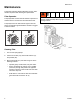
Sprayer Disassembly
1. Remove four thumbscrews (18) and remove filter
retainer (17), prefilter (20) and main filter (16). Parts,
page 14.
2. Remove two screws (101) and inlet plug (61) from
HVLP box (1). Remove three motor wire connectors
from inlet plug (61).
3. Place sprayer upside down. Remove four screws (77)
from sprayer base plate (2).
4. Pull up sprayer base plate and attached parts.
Thread motor wires that connected to inlet plug
through access in HVLP box.
5. Repair or replace any required parts.
Sprayer Assembly
1. Replace duct gaskets (59, 60) and any other dam-
aged or worn parts. Replace circuit breaker (32), if it
has cycled. Remove residual adhesive from previous
gaskets by wiping any sticky surfaces with mineral
spirits solvent (also called white spirit). Let solvent
evaporate thoroughly before installing replacement
gasket.
2. Use an adjustable square with blade running full
length of longest side of duct (22), to position duct
perpendicular to the base (2). Hold duct in place to
keep duct perpendicular to base edge and carefully
remove square.
3. Turn sprayer upside-down. Carefully slip base plate
and attached parts down into HVLP box (1).
NOTE: Be sure duct to maintain duct alignment.
4. Thread motor wires that connect with plug (61)
through access port in HVLP box.
5. Use four screws (77) to secure base plate to HVLP
box (1). Use an adjustable clamp over the outside of
HVLP box (1) to align screw holes if necessary.
6. Install three motor wire connectors onto plug (61).
Install plug (61) with two screws (101) into HVLP box
(1).
7. Install filter gaskets (19), main filter (16) with arrow
facing into HVLP box (1), pre-filter (20), filter retainer
(17), and hose rack (35) with four thumbscrews (18).
To avoid injury, including electric shock turn off sprayer
and unplug power cord before performing any repair
procedures on the turbine.
ti13061a
18
17
16
20
ti13062a
ti13063a
61
101
ti12973a
77
2