Operation, Repair, Parts FinishPro™ HVLP 7.0/9.0/9.5 313406L EN For portable spray applications of fine finish coatings. For professional use only. Not approved for use in European explosive atmosphere locations. 120 Vac Models: 256847, 256848, 256849 240 Vac Models: 256851, 256852, 256853 Maximum Working Pressure: 10 psi (0,07 MPa, 0.7 bar) Important Safety Instructions Read all warnings and instructions in this manual. Save these instructions. US Patent No.
Table of Contents Table of Contents Warnings . . . . . . . . . . . . . . . . . . . . . . . . . . . . . . . . . 3 Grounding and Electric Requirements . . . . . . . . 5 Component Identification . . . . . . . . . . . . . . . . . . . . 6 Setup . . . . . . . . . . . . . . . . . . . . . . . . . . . . . . . . . . . . . 7 Fluid Preparation . . . . . . . . . . . . . . . . . . . . . . . . . 7 Connect Fluid and Air Supply . . . . . . . . . . . . . . . 7 Pressure Relief Procedure . . . . . . . . . . . . . . . . .
Warnings Warnings The following warnings are for the setup, use, grounding, maintenance and repair of this equipment. The exclamation point symbol alerts you to a general warning and the hazard symbol refers to procedure-specific risks. Refer back to these warnings. Additional, product-specific warnings may be found throughout the body of this manual where applicable. WARNING GROUNDING This product must be grounded.
Warnings WARNING FIRE AND EXPLOSION HAZARD Flammable fumes, such as solvent and paint fumes, in work area can ignite or explode. To help prevent fire and explosion: • Do not spray flammable or combustible materials near an open flame or sources of ignition such as cigarettes, motors, and electrical equipment. • Paint or solvent flowing through the equipment is able to result in static electricity. Static electricity creates a risk of fire or explosion in the presence of paint or solvent fumes.
Warnings WARNING CALIFORNIA PROPOSITION 65 The engine exhaust from this product contains a chemical known to the State of California to cause cancer, birth defects or other reproductive harm. Grounding and Electric Requirements Use 3-wire, 12 awg, 50 ft (15 m) or shorter, extension cords with ground prong. This equipment requires a 120 Vac, 60 Hz, 15A circuit, with a grounding receptacle. Do not alter the ground prong or use an adapter.
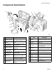
Component Identification Component Identification G S T C R E L M U N A B D H F K J P ti12858a Item A Sprayer air outlet Item Description HVLP connector for air supply to HVLP spray Gun K Resettable circuit breaker Provides protection for motor Quick connect Enables quick connection to spray gun B Sprayer power switch On/Off switch for sprayer motor L C Fluid storage compartment Provides storage for up to four fluid sets M Air valve D Sprayer handle Folds flat for minimum storag
Setup Setup Fluid Preparation Pressure Relief Procedure • Strain fluids before you spray. This includes color, reducers and hardeners. • Use a slower drying reducer or thinner to compensate for the faster drying time caused by the warm air of the turbine. Do not over reduce • Sprayer performance varies with the viscosity of the material sprayed and the length of the hose. To prevent pressure drop, use hose supplied with sprayer.
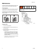
Maintenance Maintenance The sprayer system is lifetime lubricated. The only maintenance required is filter cleaning and replacement. Filter Operation The sprayer filter must be clean at all times to provide sufficient air flow to cool the motor and atomize the fluid. To avoid electric shock, never install a damp filter in the turbine. Installing a damp filter in sprayer can also damage turbine. The sprayer has an air filter indicator light on the front panel.
Troubleshooting Troubleshooting Problem No fluid delivery Cause No material, no remote cup pressurization, hose or pickup tube clogged Solution Check cup for material Check for leaks at the container gasket (1-quart remote cup cover). Tighten cover if loose. Check air flow (approximately 1/4 CFM) from male quick-disconnect at Compact outlet. Turn pressure regulator clockwise. Look for pressure on gauge. (If no pressure on gauge, check air line fittings.
Repair Repair Sprayer Disassembly 3. Place sprayer upside down. Remove four screws (77) from sprayer base plate (2). 77 2 To avoid injury, including electric shock turn off sprayer and unplug power cord before performing any repair procedures on the turbine. 1. Remove four thumbscrews (18) and remove filter retainer (17), prefilter (20) and main filter (16). Parts, page 14. ti12973a 4. Pull up sprayer base plate and attached parts.
Turbine Replacement Turbine Replacement Refer to Parts Drawing, page 14. 1. Follow Sprayer Disassembly procedure, page 10. 2. Remove gasket (21). 3. Remove three screws (14) from spacer (38). 4. Remove plate (21) and three spacers (83). 5. Remove motor wires from spade connectors. 6. Rotate motor (11) from outlet fitting (29) and lift up from spacers (41). 7. Install new gaskets (21, 23, 24, 59 and 60).
Wiring Diagrams Wiring Diagrams USA 7 3 4 N L G 1 GROUND 8 G 2 BK W 9 L G N 12 Ref. Part Description 1 2 3 4 5 6 7 8 9 10 11 12 Conductor, BK Conductor, BK Conductor, G/Y Conductor, W Conductor, W, BK, G Conductor, W Plug, inlet Circuit Breaker, 15A Plug, outlet, CompPack Light, indicator, 120V Switch, rocker Sensor, pressure 244273 15W486 15W485 15W484 257333 240256 114064 114403 15V923 114280 120660 114279 Qty 1 1 1 1 1 1 1 1 1 1 1 1 6 11 5 3 6 2 5 10 ti12765a International Ref.
Technical Data Technical Data 120 Vac, 60 Hz Ampere Watts Maximum Hose Length ft (m) FinishPro 7.0 11.0 200 40 (12,2) 28 (12,7) 38 (17,2) 94.9 dBa 82 dBa FinishPro 9.0 11.0 250 60 (18,3) 29 (13,2) 39 (17,7) 95.9 dBa 83 dBa FinishPro 9.5 13.6 300 60 (18,3) 30 (13,6) 40 (18,1) 96.3 dBa 83.4 dBa Ampere Watts Maximum Hose Length ft (m) Sprayer Weight lb (kg) Total Weight lb (kg) Sound Power* Sound Pressure* FinishPro 7.0 5,40 200 40 (12,2) 28 (12,7) 38 (17,2) 94.
Parts Parts Models 256847, 256848, 256849, 256851, 256852, 256853 4 103 3 33 102 34 6 104 100 30 105 49 89 30 8 1 63 13 62 87 25 18 77 88 61 101 19 16 20 17 18 35 77 ti12835a 14 313406L
Parts List Parts List Models 256847, 256848, 256849, 256851, 256852, 256853 Ref.
Parts Drawing Parts Drawing Models 256847, 256848, 256849, 256851, 256852, 256853 21 14 15 11 109 38 29 107 9 108, 111 48 24 41 5 31 59 90 2 39 22 64 37 45 86 106 60 30 42 44 36 46 45 58 110 32 27 56 28 23 45 14 16 ti12836d 313406L
Parts List Parts List Models 256847, 256848, 256849, 256851, 256852, 256853 Ref. Part Description 2 257066 PLATE, base, turbine, painted 5 114279 SENSOR, pressure 9 156698 O-RING 11+* TURBINE 15Y812 FinishPro 7.0, 3-stage, 120V 15Y813 FinishPro 9.0, 4-stage, 120V 15Y814 FinishPro 9.5, 5-stage, 120V 15Y815 FinishPro 7.0, 3-stage, 240V 15Y816 FinishPro 9.0, 4-stage, 240V 15Y817 FinishPro 9.5, 5-stage, 240V 14 114670 SCREW, cap, hex hd 15 194094 PLATE, turbine 21 GASKET, turbine 15W153 FinishPro 7.
Graco Standard Warranty Graco warrants all equipment referenced in this document which is manufactured by Graco and bearing its name to be free from defects in material and workmanship on the date of sale to the original purchaser for use. With the exception of any special, extended, or limited warranty published by Graco, Graco will, for a period of twelve months from the date of sale, repair or replace any part of the equipment determined by Graco to be defective.