
User's Manual
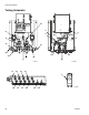
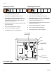

Schematic Diagrams
312780F 37
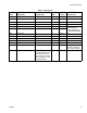
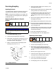
Table 6: Tubing Chart
Color Description Starting Point
Ending
Point
Tube OD
in. (mm) Tube Ref. No.
Green Dose A On A2 A2 5/32 (4) 336
Green Dose B On A4 A4 5/32 (4) 336
Green Purge A On A6 A6 5/32 (4) 336
Green Purge B On A8 A8 5/32 (4) 336
Green Dump A DA DA 5/32 (4) Included in optional
Dump Valve Kit
15V821 (Wall Panel)
or 15V822 (RoboMix)
Green Dump B DB DB 5/32 (4)
Red Dose A Off B1 B1 5/32 (4) 337
Red Dose B Off B3 B3 5/32 (4) 337
Red Purge A Off B5 B5 5/32 (4) 337
Red Purge B Off B7 B7 5/32 (4) 337
Natural Solenoid Air Supply 13 13 1/4 (6) 334
Natural Flow Control Air Supply 14 14 1/4 (6) User supplied. Con-
nects air manifold to
flow control regulator.
Natural Purge Air Supply Use as a separate line
connected directly to the
main shop air line. Do
not connect to the unit’s
main air supply or to the
air manifold (335).
AT 1/4 (6) 338