
User's Manual

Parts
312777E 49
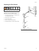
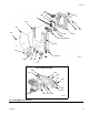
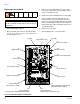
Parts
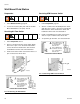
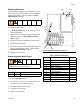
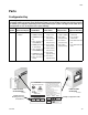
Configurator Key
The configured part number for your equipment is printed on the equipment identification labels. See the
illustrations below for location of the identification labels. The part number includes one digit from each of
the following six categories, depending on the configuration of your system.
The digits in this table do not
correspond to ref. nos. in the parts lists or parts drawings.
Manual
System Control and Display A and B Meter Color Valves Catalyst Valves Applicator Handling
M D = EasyKey with LCD
Display
0 = No Meters
1 = G3000 (A and B)
2 = G3000HR (A and
B)
3 = 1/8 in. Coriolis (A)
and G3000 (B)
4 = G3000 (A) and 1/8
in. Coriolis (B)
5 = 1/8 in. Coriolis (A)
and G3000HR (B)
6 = G3000HR (A) and
1/8 in. Coriolis (B)
7 = 1/8 in. Coriolis (A
and B)
0 = No Valves
(single color)
1 = Two Valves
(low pressure)
2 = Four Valves
(low pressure)
3 = Seven Valves
(low pressure)
4 = Twelve Valves
(low pressure)
5 = Two Valves
(high pressure)
6 = Four Valves
(high pressure)
0 = No Valves
(single catalyst)
1 = Two Valves
(low pressure)
2 = Four Valves
(low pressure)
3 = Two Valves
(high pressure)
1 = One Air Flow
Switch Kit
2 = Two Air Flow
Switch Kits
3 = One Gun Flush Box
Kit
4 = Two Gun Flush Box
Kits
6-Digit Configured Part No.
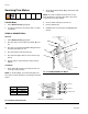
Label Location
on EasyKey
Label Location
on Fluid Station
Maximum Fluid
Working Pressure
is listed here
TI12418aTI12423a