
User's Manual

Service
46 312777E
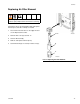
Servicing Flow Meters
Coriolis Meter
1. Follow Before Servicing, page 36.
2. To remove and service the Coriolis meter, see man-
ual 313599.
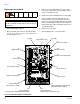
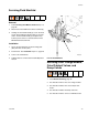
G3000 or G3000HR Meter
Removal
1. Follow Before Servicing, page 36.
2. Unscrew cable connector (CC) from meter (M). F
IG
.
23.
3. Unscrew four 1/4-20 screws (MS) holding the meter
mounting plate (MP). F
IG
. 23.
4. Unscrew fluid line from meter inlet (P).
5. Unscrew meter (M) from dose valve connector (H).
F
IG
. 23.
6. Service meter as instructed in the meter manual
308778.
Installation
1. Screw meter (M) securely onto the dose valve con-
nector (H), using a wrench.
NOTE: To avoid leakage, secure the meter (M) to the
dose valve connector (H) before connecting it to the fluid
station.
2. Secure meter (M) and plate (MP) to fluid station with
screws (MS).
NOTE: You must assemble the meter sensor to the
meter body before connecting the cable to the sensor
for the meter to function properly.
3. Connect meter cable (CC). See F
IG
. 23.
4. Connect fluid line (P).
5. Calibrate meter as instructed in ProMix Operation
manual.
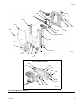
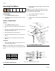
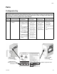
F
IG
. 23: G3000/G3000HR Flow Meters
TI12653a
CC
M
H
MP
P
MS
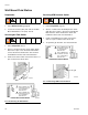
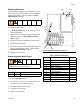
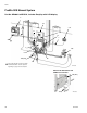
F
IG
. 24: Meter Cable Schematic
1
2
3
4
5
6
J3
PWR (RED)
COM (BLACK)
SIG (WHITE)
SHIELD/GRN
PWR (RED)
COM (BLACK)
SIG (WHITE)
SHIELD/GRN
PWR (RED)
COM (BLACK)
SIG (WHITE)
SHIELD/GRN
FLOW METER A
FLOW METER B
3X CABLE
241799-801
FLOW METER SOLVENT
1
2
3
4
5
6
J12
GROUND
TERMINAL
*Connectors on Fluid Station Control Board
*
*
Cable Length
241799 5 ft (1.52 m)
241800 16 in. (406 mm)
241801 13 in. (330 mm)