
User's Manual

Service
312777E 45
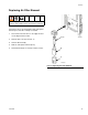
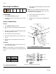
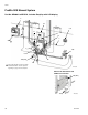
Replacing Solenoids
The Wall Mount Fluid Station has a minimum of 4 sole-
noids. If you have options installed, you have additional
(optional) solenoids for each. See Table 9 and Sche-
matic Diagrams, page 30.
To replace a single solenoid:
1. Follow Preparation, page 42, and shut off power at
main circuit breaker.
2. Disconnect 2 solenoid wires (N) from control board
(302). See F
IG
. 22 and System Electrical Sche-
matic, page 33.
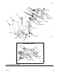
3. Unscrew 2 screws (P) and remove solenoid (313).
4. Install new solenoid (313).
5. Connect 2 wires (N) to control board (302). Solenoid
wires are polarized (red +, black –). Refer to Sys-
tem Electrical Schematic, page 33.
6. Replace the cover (322).
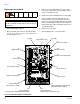
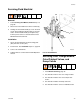
Replacing Control Board Fuses
1. Follow Preparation, page 42.
2. Locate fuse F1 or F2 on the control board. See F
IG
.
22. Remove the screw and metal strap.
3. Pull the fuse away from the board.
4. Install the new fuse (343).
5. Replace the cover (322).
Replacing a fuse (F1 or F2) with a non-Graco fuse
voids the IS system safety approval.
Fuse Part No. Description
F1, F2 123690 Fuse; 125 mA, intrinsically safe
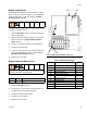
F
IG
. 22: Replacing Solenoids and Fuse
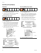
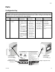
Table 9: Wall Panel Solenoids
Solenoid Actuates Fuse
Standard
1 Dose Valve A F1
2 Dose Valve B F1
3 Air Purge Valve F1
4 Solvent Purge Valve F1
Optional
5 Third Flush Valve F2
6 Dump Valve A F2
7 Dump Valve B F2
8 Gun Flush Box 1 F2
9 Gun Flush Box 2 F2
TI12652b
N
P 313
4321
302
7
8
5
6
9
343
F1
F2