
User's Manual

Troubleshooting
26 312777E
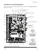
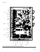
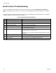
Booth Control Troubleshooting
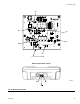
See F
IG
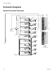
. 10 and Table 6 to troubleshoot the booth control board. Also see the System Electrical Schematic on
pages 32 and 33. The booth control does not contain any servciceable parts and must be replaced as a complete
unit.
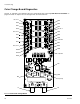
To replace the booth control, disconnect the cable from J7 on the fluid station control board. See F
IG
. 8 on page 23.
Install the new booth control and connect the cable to J7.
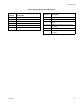
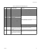
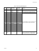
Table 6: Booth Control Board Diagnostics
LED Description Diagnosis
D2 Alarm Reset Indicator (red) LED blinks when an alarm occurs and turns off after alarm is reset.
D3 Mix Indicator (green) LED turns on when in Mix mode.
D4 Standby Indicator (green) LED turns on when in Standby mode.
D5 Purge Indicator (green) LED turns on when in Purge mode.
D6 Job Complete Indicator (green) LED blinks once after key is pressed, signalling that job is complete,
and A and B totalizers are reset.
D7 Recipe Indicator (green) LED turns on when a recipe is in use, and shuts off when a new recipe
is being selected or if an alarm occurs.
LED blinks when a new recipe is loading and turns solid after loading
is complete.
D8 Board OK (green) Blinks (heartbeat) during normal operation.
D9 Communication (yellow) Turns on when board is communicating with EasyKey.
D10 Power (green) Turns on when power is supplied to the board (J11).