
User's Manual


Repair
40 312760S
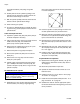
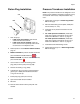
7. If there is only one fluid control module on the
machine, set the rotary switch (S) to 1. See F
IG. 14.
If there are two fluid control modules, set the
rotary switch (S) to 1 on the module closest to the
air regulator and set the rotary switch (S) to 2 on the
other module. See F
IG. 14.
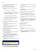
8. Install access cover (D).
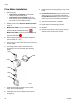
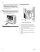
Fuse Replacement
1. Remove incoming power cord from machine.
2. Insert a flat-head screw-driver between the fuse
holder and the back of the incoming power bracket
remove machine fuse holder.
3. Remove the blown fuse from the machine fuse
holder.
4. Install new fuse with same rating into the fuse
holder.
5. Install the fuse holder into the Incoming Power
Bracket.
The rotary switch setting must only be adjusted on
new fluid control modules after installation. The
rotary switch setting indicates the fluid control mod-
ule number being replaced. The fluid control mod-
ule uses a 16-position rotary switch.
F
IG. 14
S
ti12335a
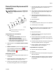
Fuse Holder
Fuse holder is located between the
power connector and power switch.
1
1
ti12563a