
User's Manual


Repair
312760S 39
Fluid Control Module
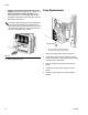
Replacement
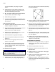
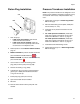
1. Remove access cover (D).
2. Remove two screws (C) and FCM (A) from base (B).
3. Mount base (B) to system with four screws. Insert
screws through top of base and tighten to system.
4. Mount FCM (A) on base (B) with two screws (C).
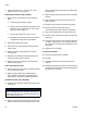
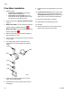
5. Connect cables to front of fluid control module. See
F
IG. 12 and the following table.
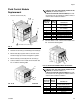
6. Connect cables to rear of fluid control module. See
F
IG. 13 and the following table.
FIG. 11
F
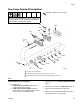
IG. 12: Fluid Control Module Front Connections
D
C
C
A
B
1
Not visible from current angle.
1
ti12334a
ti12337a
1
3
4
2
If there is only one fluid control module on the
machine, the module number is 1.
If there are two fluid control modules, the mod-
ule closest to the air regulator is module number 1
and the other module is number 2.
Connection
Reference
(FIG. 12)
Module
Number Connects To
1 1 Footswitch or
PLC Interface
2 1 Footswitch or
PLC Interface
3 1 Tank Low Level Sensor A
4 1 Tank Low Level Sensor B
1 2 Flow Meter A
2 2 Flow Meter B
3 2 Tank High Level Sensor A
4 2 Tank High Level Sensor B
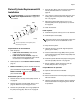
FIG. 13: Fluid Control Module Rear Connections
If there is only one fluid control module on the
machine, the module number is 1.
If there are two fluid control modules, the mod-
ule closest to the air regulator is module number 1
and the other module is number 2.
Connection
Reference
(F
IG. 13)
Module
Number Connects To
5 1 Dispense Valve and
Linear Position Sensor
6 1 Pressure Transducer A
7 1 Pressure Transducer B
5 2 Auto-Fill Valve
6 2 Not Used
7 2 Not Used
ti12336a
5
6
7