
User's Manual


Repair
312760S 37
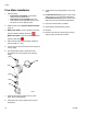
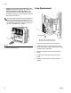
Piston Plug Installation
1. Drain the pump.
• If ball valves are installed, close the ball
valves then take several shots.
• If ball valves are not installed, empty the
tanks. Perform shots repeatedly until no mate-
rial comes out of the dispense valve.
2. Relieve pressure. See Pressure Relief Procedure,
page 14.
3. Models with ADM: To prevent machine movement,
press the Machine Disable Mode key ( ).
Models with SDM: To prevent machine movement,
press the Red button
.
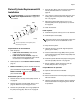
4. Use a wrench to remove the existing piston
plug (1801) from the pump end cap (508).
5. Remove the existing o-ring (1802).
6. Lubricate the new o-ring with a high temperature
grease (part 115982) and install the lubricated
o-ring into the end cap.
7. Install pump plug (1801) into end cap.
8. Open the tank ball valves if installed.
9. Fill tanks.
10. Perform several shots to fill the pump with new
material.
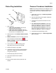
Pressure Transducer Installation
NOTE: The pressure transducers are designed to work
with the hoses available in the PR70 configurator. If they
are used with other hoses, unexpected alarms may
occur.
1. Follow steps 1 through 6 of Piston Plug Installa-
tion on this page.
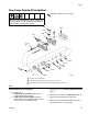
2. Remove shield locking screws (2202, 2409) then
remove shield (117, 214).
3. Install hex end of pressure transducer into end
cap (508).
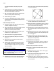
4. For A side pressure transducers, install data
cable end of pressure transducer into port #6 of
Fluid Control Module #1. See F
IG. 5, page 27.
For B side pressure transducers, install data
cable end of pressure transducer into port #7 of
Fluid Control Module #1. See F
IG. 5, page 27.
5. Install shield and shield locking screws.
6. Follow steps 8 through 10 of Piston Plug Installa-
tion on this page.
1802
1801
ti12562a
508