
User's Manual


Repair
312760S 31
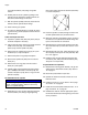
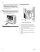
Air Cylinder Kit Installation
Prepare Machine for Kit Installation
1. Relieve pressure. See Pressure Relief Procedure,
page 14.
2. Shut down the machine. See Shutdown, page 14.
3. Disconnect the pressurized air input hose.
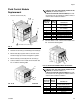
4. Remove shroud screws (2202, 2409). See F
IG. 17
on page 44 and F
IG. 21 on page 49.
5. Remove the shroud (117, 214). See F
IG. 16 on
page 42 and F
IG. 21 on page 49.
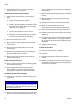
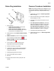
Disassemble the Air Cylinder
6. Remove the incoming power bracket (110) from the
machine by removing the two attachment
screws (109). See F
IG. 15 on page 41.
7. Remove the two solenoid valves (407, 408) from the
cylinder blind end block (418) by removing the three
socket head cap screws (402).
8. Use an open-end wrench to remove all hex
nuts (103, 100b, 100d) connecting the piston rod to
the drive block. See F
IG. 15 on page 41.
9. Remove the four screws (108) that attach the cylin-
der rod end block (417) to the frame. See F
IG. 15 on
page 41. Access the screws through the four holes
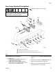
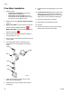
416
411
418
404
414
415
409
410
412
414
402
407
412
422
415
413
412
420
405
401
417
412
411
403
419
406
408
Torque to 41 in-lb (4.6 N•m).
Torque to 350 in-lb (39.5 N•m).
Torque to 100 ft-lb (135 N•m).
Coat all sliding surfaces with lubricant, part 115982.
Apply sealant tape to npt fittings.
1
2
3
4
5
2
1
4
4
4
ti12490a
See Kits on page 80 for kit numbers.