
User's Manual


Electrical Schematics
28 312760S
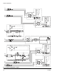
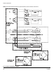
NOTE: See PR70 operation manual for Optional External Control Interface instructions.
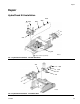
F
IG. 6: Electrical Schematic - Page 4
2
1
4
5
1
3
2
4
5
1
3
2
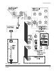
Customer Supplied
Dry Contact/Relay
Customer Supplied
Dry Contact/Relay
SHOT SEL - BIT 0
SHOT SEL - BIT 3
Not Used
COMMON
SHOT SEL - BIT 1
SHOT REQUEST - INPUT
FAULT OUTPUT
INTERRUPT - CAN - REQ - INPUT
COMMON
READY - OUTPUT
Brown
Gray
Black
Blue
White
Brown
+24 VDC
+24 VDC
Gray
Black
Blue
White
NOTE: Connector #1 is for use
with all systems.
NOTE: View shown is looking at
pins on end of cable.
NOTE: Connector #2 is for use
with systems with an Advanced
Display Module only.
NOTE: View shown is looking at
pins on end of cable.