
User's Manual

Setup
312759R 51
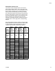
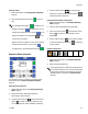
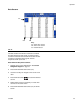
Shot Number Selection Lines
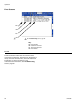
The external control interface has four lines used to
select a shot number (“SHOT - SEL - BIT” lines in F
IG.
32, Connector #2, Pins #1, 2, 4, 5). The default for each
line is a “high” +24 VDC output. To select a shot, the
external control will need to ground a certain combina-
tion of lines to the Return line (Connector #2, Pin #3) for
at least 0.100 seconds to create a “low” signal for each
line. Each combination refers to one shot number from
Shot #1 to Shot #15. If all lines are “high” the shot
selected on the display module is used. See the follow-
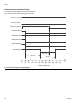
ing table. See F
IG. 34 on page 52 for a sample timing
diagram.
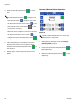
For system software versions 1.06.007 or later, the Shot
Number Selection lines cannot be used to select invalid
or undefined shot numbers. Attempting to select an
invalid or undefined shot number will be rejected.
Shot
Number
Selected
SHOT -
SEL -
BIT0
(Conn. #2,
Pin #1)
SHOT -
SEL -
BIT1
(Conn. #2,
Pin #2)
SHOT -
SEL -
BIT2
(Conn. #2,
Pin #4)
SHOT -
SEL -
BIT3
(Conn. #2,
Pin #5)
None /
Display
Module
selec-
tion.
High High High High
1
Low High High High
2High
Low High High
3
Low Low High High
4 High High
Low High
5
Low High Low High
6High
Low Low High
7
Low Low Low High
8 High High High
Low
9
Low High High Low
10 High
Low High Low
11
Low Low High Low
12 High High
Low Low
13
Low High Low Low
14 High
Low Low Low
15
Low Low Low Low