Instructions LDM5 (Standard) & LDP5 (Preset) Electronic Metered Dispense Valves 312668W EN For metered dispense of oils and antifreeze. For professional use only. Not approved for use in European explosive atmosphere locations. Models: See page 2 1000 psi (7 MPa, 69 bar) Maximum Working Pressure 5 gpm (19 lpm) Maximum Flow Rate Important Safety Instructions Read all warnings and instructions in this manual. Save these instructions.
Models Models 2 Extension Meter Model No.
Warnings Warnings The following warnings are for the setup, use, grounding, maintenance, and repair of this equipment. The exclamation point symbol alerts you to a general warning and the hazard symbol refers to procedure-specific risk. Refer back to these warnings. Additional, product-specific warnings may be found throughout the body of this manual where applicable. WARNING SKIN INJECTION HAZARD High-pressure fluid from dispense valve, hose leaks, or ruptured components will pierce skin.
Warnings WARNING PERSONAL PROTECTIVE EQUIPMENT Wear appropriate protective equipment when in the work area to help prevent serious injury, including eye injury, hearing loss, inhalation of toxic fumes, and burns. Protective equipment includes but is not limited to: • Protective eyewear, and hearing protection. • Respirators, protective clothing, and gloves as recommended by the fluid and solvent manufacturer.
Installation Installation Typical Installations NOTICE FIG. 1 shows a typical hose reel installation. Dispense valves can also be installed on a console as shown in Fig. 2. The typical installation shown in Fig. 1 is only a guide. It is not a complete system design. Contact your Graco distributor for assistance in designing a system to suit your needs.
Installation Pressure Relief Procedure Pre–Installation Procedure 1. Install the battery. See Replacing the Battery on page 31. 2. Follow the Pressure Relief Procedure. The equipment stays pressurized until pressure is manually relieved. To reduce the risk of serious injury from pressurized fluid, accidental spray from the dispense valve, or splashing fluid, follow this Pressure Relief Procedure when you: • • • 3. Close the shut–off valve (B, FIG. 1, page 5). 4. Ground the hose and reel or console.
Installation 4. a. Place the hose end (with no dispense valve connected) into a container for waste oil. b. Secure the hose in the container so it will not come out during flushing. c. If you have multiple dispense positions, first flush the dispense position farthest from the pump, then work your way toward the pump.
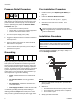
Installation Installing Extension and Nozzle on Meter B 26a 26c 26b ti12081a FIG. 8 FIG. 7 1. Thread the sealing nut (26c) onto the extension (26a). 2. Thread extension into meter outlet at least three full turns to tighten securely. (FIG. 7). (Over torquing may cause casting meter to split) NOTICE • Do not overtighten extension to sealing nut. Over tightening may cause meter casting to split. • Do not use a twist/lock or manual shut-off nozzle.
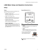
LDM5 Meter Setup and Operation Instructions LDM5 Meter Setup and Operation Instructions Setup Terms Keypad Buttons (FIG. 9) The following terms are shown on the display and/or used often in this instruction manual. • R-TOTAL: Resettable Total Shows the cumulative amount that has been dispensed. Can be reset to zero. • TOTAL: Non–Resettable Total Shows the cumulative amount that has been dispensed for the life of the unit. Cannot be reset.
LDM5 Meter Setup and Operation Instructions Setup Menus (FIG. 10) c. AUTO PTS QTS GAL LITERS R-TOTAL Min. Dispense Volume 0.5 liter (0.13 gal) Minimum Flow Rate 1.0 l/min. (0.26 gpm) Maximum Flow Rate 19.0 l/min. (5.00 gpm) Maximum Working Pressure: 70 bar (1000 PSI) FIG. 10 Press and hold Reset button again to display Calibration Menu. When this menu is displayed CAL blinks on the screen (FIG. 13). The total that is displayed when you leave each menu is the total that is stored.
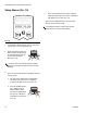
LDM5 Meter Setup and Operation Instructions Resettable Total (FIG. 11) Units of Measurement (FIG. 12) Resets dispensed total on screen to zero or stores displayed dispense total. The resettable total accumulates until the next time it is manually reset. Sets unit of measurement to quarts, gallons, pints, or liters. Auto PTS QTS GAL LITERS R-TOTAL AUTO PTS QTS GAL LITERS R-TOTAL Min. Dispense Volume 0.5 liter (0.13 gal) Minimum Flow Rate 1.0 l/min. (0.26 gpm) Maximum Flow Rate 19.0 l/min. (5.
LDM5 Meter Setup and Operation Instructions Calibration (FIG. 13) Recalibrates the meter for dispensing different fluids. CAL b. Press and hold Total button until CAL stops blinking and the display shows 1.00. c. When CAL starts to blink again, the display should show 1.00. The new calibration is complete. PTS QTS GAL LITERS R-TOTAL If an error was made during meter recalibration, repeat Steps a - c of the recalibration process to recalibrate the meter again. Min. Dispense Volume 0.5 liter (0.
LDM5 Meter Setup and Operation Instructions Operation Dispensing Fluid in Standard Mode All buttons are disabled while fluid is being dispensed. AUTO 3. Squeeze the trigger. Fluid begins to flow, and the amount shown on the display counts up from zero. PTS QTS GAL LITERS R-TOTAL AUTO Min. Dispense Volume 0.5 liter (0.13 gal) Minimum Flow Rate 1.0 l/min. (0.26 gpm) Maximum Flow Rate 19.0 l/min. (5.00 gpm) Maximum Working Pressure: 70 bar (1000 PSI) PTS QTS GAL LITERS R-TOTAL Min. Dispense Volume 0.
LDM5 Meter Setup and Operation Instructions Viewing Totals This is the procedure for viewing the non–resettable and resettable totals in gallons or liters. To change the resettable total, see Resettable Total, page 11. AUTO 1. If display is blank (in sleep mode), press and hold either the Total or Rest button. AUTO PTS QTS GAL LITERS R-TOTAL Min. Dispense Volume 0.5 liter (0.13 gal) Minimum Flow Rate 1.0 l/min. (0.26 gpm) Maximum Flow Rate 19.0 l/min. (5.
LDM5 Meter Setup and Operation Instructions Error Code If an error code is shown on the display, as shown in FIG. 19, you can press the Reset button to clear the error code and view the dispensed amount. Even in an error condition, the unit keeps track of the amount dispensed. AUTO PTS QTS GAL LITERS R-TOTAL Min. Dispense Volume 0.5 liter (0.13 gal) Minimum Flow Rate 1.0 l/min. (0.26 gpm) Maximum Flow Rate 19.0 l/min. (5.00 gpm) Maximum Working Pressure: 70 bar (1000 PSI) ti12051a FIG.
LDP5 Meter Setup and Operation Instructions LDP5 Meter Setup and Operation Instructions Setup Locking and Unlocking the Trigger Terms The following terms are shown on the display and/or used often in this instruction manual. ti11349a Locked Position • R-TOTAL: Resettable Total Shows the cumulative amount that has been dispensed in all modes. Can be reset to zero. • TOTAL: Non–resettable Total Shows the cumulative amount that has been dispensed in all modes for the life of the unit. Cannot be reset.
LDP5 Meter Setup and Operation Instructions Setup Menus (FIG. 23) Keypad Buttons (FIG. 22) AUTO PTS QTS GAL LITERS R-TOTAL AUTO PTS QTS GAL LITERS R-TOTAL ti12052a FIG. 22 • Manual / Reset* Used to select Manual Mode dispensing (see Terms). The first push selects the mode, and the second push resets the display to zero. • Auto / Reset* Used to select Auto Mode dispensing (see Terms). The first push selects the mode, and the second push resets the display to zero.
LDP5 Meter Setup and Operation Instructions c. Press and hold the Auto / Reset button again to display the Calibration Menu (FIG. 26, page 19). When this menu is displayed CAL will blink on the screen. Resettable Total (FIG. 24) Resets the dispense total to zero or stores the displayed dispense total. The resettable total accumulates until the next time it is manually reset. d. Press the Auto / Reset button again to display the Auto Preset Amount Menu (FIG. 27, page 20).
LDP5 Meter Setup and Operation Instructions Units of Measurement (FIG. 25) Calibration (FIG. 26) Sets the units of measurement to gallons, quarts, pints, or liters. Recalibrates the meter for dispensing different fluids. AUTO PTS QTS GAL LITERS R-TOTAL CAL PTS QTS GAL LITERS R-TOTAL ti12055a ti12056a FIG. 25 FIG. 26 1. If the Units of Measurement Menu is not already displayed, do steps 1- 3 in Setup Menus section, page 17. 1.
LDP5 Meter Setup and Operation Instructions 3. Do ONE of the following. b. Press and hold the Manual / Reset button until CAL stops blinking. a. To enter a new auto preset amount press and hold the 10 button to change the 10’s digit, c. When CAL starts to blink again, the display should show 1.00, which indicates the new calibration is complete. the 1.
LDP5 Meter Setup and Operation Instructions Shut–Off Default Amount (FIG. 28) 3. Do ONE of the following. Prevents accidental overfills when dispensing with the trigger locked in Manual mode. The shut–off default amount is factory preset at 5 quarts. AUTO a. To enter a new shut–off default amount, press and hold the 10 button to change the 10’s digit, PTS QTS GAL LITERS R-TOTAL the 1.0 button to change the 1’s digit, and the 0.1 button to change the first decimal digit. You cannot enter zero.
LDP5 Meter Setup and Operation Instructions Operation Fluid flows, and the amount displayed counts up from zero or the previously dispensed amount. AUTO PTS QTS GAL LITERS R-TOTAL 4. Release/unlock the trigger when you have dispensed the desired amount of fluid. Fluid flow stops. The amount you have dispensed is displayed. You may press and hold the Manual/Reset button again to reset the displayed amount to zero. ti12053a FIG. 29 Dispensing Fluid in Manual Mode (FIG. 29) 1.
LDP5 Meter Setup and Operation Instructions Dispensing Fluid in Auto Mode (FIG. 30) AUTO a. Press and hold the Auto/Reset button to set the display to zero. PTS QTS GAL LITERS R-TOTAL b. Press the10 button to change the 10s digit, ti12057a FIG. 30 press the 1.0 button to change the 1s digit, NOTICE Before you begin a preset dispense cycle, make sure AUTO is displayed.
LDP5 Meter Setup and Operation Instructions Viewing Totals Non-Resettable Totals This is the procedure for viewing the non–resettable and resettable totals. To change the resettable total, see Resettable Total on page 18. AUTO PTS QTS GAL LITERS R-TOTAL 1. If the display is blank (asleep), press and hold the Manual/Reset or Auto/Reset button to wake it up. Resettable Totals ti12060a FIG. 32 AUTO PTS QTS GAL LITERS R-TOTAL 3.
LDP5 Meter Setup and Operation Instructions Error Codes Error codes are listed below. Even in an error condition, the unit keeps track of the amount dispensed. With any error code displayed, as shown at right, you can: • Press the Manual/Reset button. Error code is cleared, unit switches into Manual mode, and dispensed amount is displayed. • Press the Auto/Reset button. Error code is cleared, unit switches into Auto mode, and the preset amount is displayed.
Troubleshooting Troubleshooting Relieve Pressure Relief Procedure, page 5, before you check or repair the meter. Be sure all other valves and controls and the pump are operating properly. Problem Battery icon is displayed. Cause Battery is low. Solution Replace the battery. See Replacing the Battery, page 31. Battery icon is blinking, and bAtt Battery is dead or is not suited for this (BATT) is blinking. application (poor quality). Replace the battery. See Replacing the Battery page 31.
Troubleshooting Problem Meter leaks from Cover/Control Cause Poor swivel (3)/hose connection. Apply PTFE tape (leave minimum 2 engaged threads uncovered for electrical continuity) or sealant to threads of hose and tighten the connection. See step 9 in Installation Procedure. Poor swivel (3)/meter housing connection. Torque the fitting to 20-25 ft-lb (27 to 34 N•m). Damaged valve stem assembly. Replace or clean valve stem and O-rings. Order Valve Repair Kit 240453. Poor seal at meter housing plate.
NOTES NOTES 28 312668W
Parts Parts FN Part No.
Parts 1 34 Models 256215, 256216, 24F882, 24F884, 24F888, 24F890 26: Rigid Extension Kit: 239949 8b 6 8a 2 4 4 8 5 3 11a 26c 11b 26a 11 11c 11d 11e 26c 11f 3 2 26a 17 1 26b 32 38 35 26b 1 26: Flexible Extension Kit: 239951 Models 255751, 255277, 258693, 258694, 24F885, 24F886, 24F891, 24F892, 255751, 255277, 24F881, 24F883, 24F887, 24F889 30 Torque to 7 to 10 in.-lb (0.8 to 1.1 N•m) 2 Torque to 140 to 150 in.
Service Service Replacing the Battery Security Seal NOTICE Do not change the battery while anything is shown on the display. You must wait until the unit falls asleep and the display is blank before you remove the battery. If you remove the battery while something is shown on the display, that information will be lost from memory. Tabs for tamper-evident security seals, one on each side of meter, prevent opening the cover. ti11363a FIG.
Technical Data Technical Data Flow range* 0.1 to 5 gpm (0.4 to 19 lpm) Maximum Working Pressure 1000 psi (69 bar) Weight 3 lbs (1.36 kg) Dimensions without extension/nozzle Length Width Height 11 inches (28 cm) 3.25 inches (8.3 cm) 3.25 inches (8.
Notes Notes 312668W 33
Graco Extended Dispense Valve Warranty Graco warrants all equipment referenced in this document which is manufactured by Graco and bearing its name to be free from defects in material and workmanship on the date of sale to the original purchaser for use. Graco will, for a period of two (2) years from the date of sale, repair or replace any non-electronic part of the equipment determined by Graco to be defective.