
User's Manual

Priming and Calibration
312393G 14 of 50
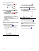
10. The machine pistons should extend slowly until they
encounter the cylinder entrance and a number
between 2000 to 2400 should appear for ‘H’.
11. If the pistons do not move, manually move the
piston by pulling on the machine drive block, until
mechanical resistance is encountered at the
cylinder entrance.
12. Press
to accept the number or to keep the
current number.
13. Adjust the Air Pressure Regulator back to a
reasonable value for proper machine operation.
14. Press
twice to return to the Run screen.
Phasing (C2)
To enable the machine to dispense the correct ratio of
material from the A and B tanks and to mix properly,
both materials will need to enter the static mixer at the
same time. Phasing shots will need to be executed to
visually verify that the 2 materials are exiting the
dispense valve at the same time.
Remove any static mixer attached to the dispense
valve, and replace it with a ratio check nozzle. Place a
waste container under the valve to capture any
dispensed material.
From the Run screen, press
, then press , and then
press
once. The following will screen will be displayed.
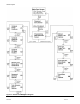
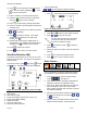
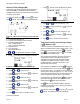
Figure 12: Phasing Calibration Screen (C2)
Key:
A A material leads B ICON
B Adjust B side Forward ICON
C B material leads A ICON
D Adjust A side Forward ICON
E A and B Exit the Same Time ICON
F Do NO Mechanical Adjustment ICON
G Phase Shot Request ICON
I Screen Number (C2)
J
& keys will navigate to adjacent screens.
K Decrease Phase Shot Percentage Amount ICON
L Current Phase Shot Percentage Amount
M Increase Phase Shot Percentage Amount ICON
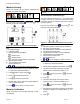
1. Select the location where the piston will reverse
(from the extend to retract motion) by pressing
or
keys. Pressing will decrease the phasing
shot. Pressing
will increase the phasing shot. A
“+” value indicates that the piston will reverse beyond
the cylinder entrance. A “-“ value indicates the piston
will reverse prior to reaching the cylinder entrance.
2. Press
(green) or the footswitch.
3. During the shot execution, visually monitor the 2
materials exiting the ratio check nozzle. If the
timing of the 2 materials exiting the nozzle cannot
be properly observed, press
or accordingly,
then repeat step 2.
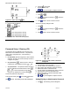
4. If the A side material exits the ratio nozzle before
the B side material (“
”), turn the B piston
Phase Adjustment Screw/ Locking nut and shaft
counterclockwise to move the B piston forward, as
indicated on the
ICON. Slight adjustments in
the piston shaft will be significant. Adjustments of a
quarter turn are typical.
5. If the B side material exits the ratio nozzle before
the A side material (“
”), turn the A piston
Phase Adjustment Screw/ Locking nut and shaft
counterclockwise to move the A piston forward, as
indicated on the
ICON.
6. Repeat step 2 until both materials exit the ratio
check nozzle at the same time (“
”).
7. Press
twice to return to the Run screen.
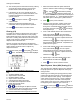
Open Dispense Valve (ODV) Setting (C3)
The next step in the calibration process is to determine
the proper position to open the Dispense Valve (DV)
during the shot.
Advancing or increasing the opening position (in milli-
meters) will build more pressure in the material hoses
prior to the dispense valve opening. If the Dispense
Valve opens too late in the shot, a surge of material
can occur or the piston could stall. If the Dispense
Valve opens to early in the shot, material “drooling” at
the beginning of the dispense cycle could occur.
From the Run screen, press
, then press , and then
press
2 times. The following screen will be displayed.