
User's Manual


Displacement Pump
24 312226L
Displacement Pump
See manual 309277 for pump repair instructions.
Removal
1. Flush pump.
2. Relieve pressure, page 7.
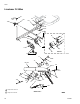
3. F
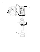
IG. 11. Remove suction tube (34) and hose (26).
4. F
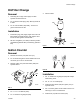
IG. 12. Push magnet ring (222) up. Push retaining
spring (194) up. Push out pin (249).
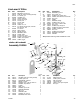
5. F
IG. 13. Loosen jam nut. Unscrew pump.
Installation
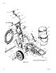
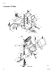
1. FIG. 14. Screw jam nut to bottom of pump threads.
Screw pump completely into manifold. Unscrew
pump from manifold until pump outlet aligns with
hose. Hand tighten jam nut, then tap 1/8 to 1/4 turn
with hammer or torque to 200 ft-lb (270 N•m).
2. F
IG. 15. Slowly pull engine starter rope until pump rod
pin hole is aligned with hydraulic rod hole. F
IG. 12.
Push pin (249) into hole. Push magnet ring (222)
down. Push retaining spring (194) into groove.
3. F
IG. 16. Fill packing nut with Graco TSL.
FIG. 11
CAUTION
Gallon counter may error if magnet ring and/or sensor
assembly are damaged during disassembly/assembly.
FIG. 12
TI6514a
34
26
249
TI6515a
222
194
FIG. 13
CAUTION
If the pump jam nut loosens during operation, the
threads of the hydraulic motor manifold will be dam-
aged. Tighten jam nut as specified.
FIG. 14
FIG. 15
TI6516a
TI6517a
TI6518a
222