
User's Manual

Pressure Control
312195K 17
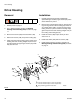
Pressure Control
On/Off Switch
Note: A complete wiring diagram is on page 34.
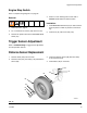
Removal
1. Relieve pressure, page 6.
2. F
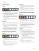
IG. 13. Remove two screws (125) and cover (31).
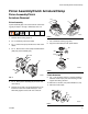
3. Remove three screws (125) from control plate (15a).
Slide control plate out to access ON/OFF switch
(15g).
4. Press locking tab on ON/OFF switch connector (B)
and disconnect from control board.
5. Press in on two retaining tabs on each side of
ON/OFF switch and remove switch.
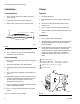
Installation
1. Install ON/OFF switch (15g) so tabs of switch snap
into place on inside of pressure control housing.
2. Connect ON/OFF switch connector (B) to J3 on con-
trol board.
3. Slide control plate (15a) back to original position
and secure with three screws (125).
4. Install cover (31) with two screws (125).
FIG. 13
TO ENGINE
GROUND
Main Control
Box Cable
Transduser
15o
15r
15g
15n
15i
B
D
15j
31
216
217
125
15d
C
A
TI6408b
125
15a
15f