Instructions–Parts List MODEL 482 Automatic Metering Valves 310543E Used to provide precise dispense of medium– to high–viscosity sealants and adhesives in a non–hazardous location. 3200 psi (22.0 MPa, 220 bar) Maximum Fluid Working Pressure Part No. C02021, Series B Model 482–B 7/8–18 uns externally threaded fluid inlet boss and 7/16–20 unf mounting hole 1/4 npt(f) material inlet, 1/8 npt(f) material outlet Part No.
Table of Contents Warnings . . . . . . . . . . . . . . . . . . . . . . . . . . . . . . . . . . . . . . 3 Setup . . . . . . . . . . . . . . . . . . . . . . . . . . . . . . . . . . . . . . . . . 5 Ground the System . . . . . . . . . . . . . . . . . . . . . . . . . 5 Installation . . . . . . . . . . . . . . . . . . . . . . . . . . . . . . . . . 5 Operation . . . . . . . . . . . . . . . . . . . . . . . . . . . . . . . . . . . . . 6 Pressure Relief Procedure . . . . . . . . . . . . . . . . . . .
Symbols Warning Symbol Caution Symbol WARNING CAUTION This symbol alerts you to the possibility of serious injury or death if you do not follow the instructions. This symbol alerts you to the possibility of damage to or destruction of equipment if you do not follow the instructions. WARNING EQUIPMENT MISUSE HAZARD INSTRUCTIONS Equipment misuse can cause the equipment to rupture, malfunction, or start unexpectedly and result in serious injury. This equipment is for professional use only.
WARNING SKIN INJECTION HAZARD Spray from the metering valve, hose leaks, or ruptured components can inject fluid into your body and cause extremely serious injury, including the need for amputation. Splashing fluid in the eyes or on the skin can also cause serious injury. Fluid injected into the skin might look like just a cut, but it is a serious injury. Get immediate surgical treatment. Do not point the metering valve at anyone or at any part of the body.
Setup Ground the System WARNING FIRE AND EXPLOSION HAZARD To reduce the risk of a fire, explosion, and serious injury, proper electrical grounding of every part of your system is essential. Read the warning section, FIRE AND EXPLOSION HAZARD, on page 4 and follow the grounding instructions below. The following grounding instructions are minimum requirements for a basic dispensing system. Your system may include other equipment or objects which must be grounded.
Operation Pressure Relief Procedure WARNING INJECTION HAZARD The system pressure must be manually relieved to prevent the system from starting or spraying accidentally. Fluid under high pressure can be injected through the skin and cause a serious injury.
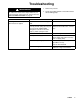
Troubleshooting WARNING To reduce the risk of serious injury whenever you are instructed to relieve pressure, always follow the Pressure Relief Procedure on page 6. 1. Relieve the pressure. 2. Check all possible problems and solutions before disassembling pump. Problem Cause Solution Metering valve fails to dispense when actuator is tripped. Check nozzle for cured or foreign fluid. Clean or clear nozzle. Observe the action of the needle Adjust the piston stroke.
Service AMV Disassembly This procedure describes how to disassemble the automatic metering valve. Refer to Parts information on pages 13 and 14. NOTE: The numbers in parentheses in the text refer to reference numbers in the parts drawings and parts lists. NOTE: Needle Chuck Tool 918482 is available. Order separately. See page 17.
Service AMV Reassembly This procedure describes how to reassemble the automatic metering valve. Refer to Parts information on pages 13 and 14. NOTES: The numbers in parentheses in the text refer to reference numbers in the parts drawings and parts lists. Repair Kit C02023 is available for AMV Part Nos. C02021, C02022, and C02025. For the best results, use all the new parts in the kit when repairing the AMV. Parts included in the kit are marked with an asterisk, for example (11*). See page 13.
Service AMV Disassembly (C02026) 1. Disconnect the tubing (104) from the elbow (102). This procedure describes how to disassemble the pistol grip metering valve. Refer to Parts information on page 15. 2. Remove the socket-head screw (107) and the second screw (not listed) that secures the metering valve (101) to the mounting block (113). Remove the metering valve. NOTE: The numbers in parentheses in the text refer to reference numbers in the parts drawings and parts lists.
Service AMV Reassembly (C02026) This procedure describes how to reassemble the pistol grip metering valve. Refer to Parts information on page 15. NOTES: The numbers in parentheses in the text refer to reference numbers in the parts drawings and parts lists. Clean all the parts thoroughly before reassembling the AMV. Check them carefully for damage or wear, replacing parts as needed. Metering Valve Reassembly Procedure To reassemble the metering valve, refer to the AMV Reassembly procedure on page 9.
Service AMV Disassembly (C02027) AMV Reassembly (C02027) This procedure describes how to disassemble the automatic metering valve. Refer to Parts information on page 16. This procedure describes how to reassemble the automatic metering valve. Refer to Parts information on page 16. NOTE: The numbers in parentheses in the text refer to reference numbers in the parts drawings and parts lists.
Parts Part Nos. C02021, C02022, and C02025 Ref. No. 1 2 Part No. Description C02029 C02028 C02043 BODY; used on C02022, C02025 BODY; used on C02021 RETAINER, outlet; used on C02021 and C02022 RETAINER, outlet; used on C02025 CAP, cylinder PISTON, air NEEDLE VALVE, lapped; includes items 6a, 6b, and 6c . PISTON, fluid . NEEDLE . SEAL SCREW, stop NUT, lock WASHER, back-up C02044 3 4 6 C02041 C02045 C02036 6a 6b 6c 7 8 9 n/a n/a n/a C02030 C02042 C02035 Qty. 1 1 1 1 1 1 1 1 1 1 1 1 Ref. No.
Parts Part No. C02078 Model 482–DA; with double acting air cylinder and 1/4 npt(f) outlet Ref. No. Part No. Description 1 2 3 4 5 6 C02079 C02044 C02077 C02074 C02076 C02036 6a 6b 6c 7 8 9 10 11 n/a n/a n/a C02030 C02042 C02035 114027 C02032 BODY, valve, meter RETAINER, outlet CAP, cylinder PISTON, air CYLINDER NEEDLE VALVE, lapped; includes items 6a, 6b, and 6c . PISTON, fluid . NEEDLE . SEAL SCREW, stop NUT, lock WASHER, back-up WASHER, flat no. 6 NUT, lock nylon no. 5–40 Qty.
Parts Part No. C02026 Model 482–HA; Model 482–C with trigger-actuated pistol grip handle Ref. No. Part No. Description 101 102 103 104 105 106 107 C02022 C20850 C19955 192331 C20861 104636 C20023 METERING VALVE ELBOW SOCKET-HEAD SCREW TUBING FITTING (10-32 x 1/8 in.) VALVE SOCKET-HEAD SCREW Qty. C02026 1 1 4 1 1 1 1 Ref. No. Part No. Description 108 109 110 111 112 113 C02039 C26312 C04083 C20065 101503 C02040 HANDLE TRIGGER SPRING ROLL PIN ROLL PIN MOUNTING BLOCK Qty.
Parts Part No. C02027 AMV for use with moisture sensitive materials. This AMV is designed to be used with moisture sensitive materials. 203 Ref. No. Part No. Description 201 C02021 202 203 204 205 206 C04104 C26069 C20477 C20479 C19888 AUTOMATIC METERING VALVE CARTRIDGE; 2.5 oz END CAP HEX NIPPLE; 1/8 npt HEX NIPPLE; 1/4 npt 90 REDUCING ELBOW 1/8 x 1/4 npt SCREW, cap, socket-head; 7/16–20 x 3/4 in. long SEAL FLUID 207 C20023 208 206995 2.75 in. (70 mm) approx. fill level Qty.
Accessories Use Only Genuine Graco Parts and Accessories Fluid Nozzles These nozzles fit all automatic metering valves covered in this manual. Orifice Size Nozzle Part No. Adapter Part No. 3/64 in. (1.2 mm) C17008; 1/8 npt(m) not required 3/32 x 3/8 in. (2.4 x 9.5 mm) C01025; 1/8 npt(m) not required 1/16 in. (1.
Technical Data Category Data Maximum fluid working pressure 3200 psi (22.0 MPa, 220 bar) Minimum fluid working pressure 50 psi (0.34 MPa, 3.4 bar) Minimum air supply pressure 80 psi (0.55 MPa, 5.5 bar) Viscosity range 3000 to 1 million centipoise Shot size range 0.2 to 4.0 cc Shot cycle rate 15 shots per minute, at 4.
Dimensions C02021, C02022, and C02025 Metering Valves 5.50 in. max., 5.19 in. min. (139.7 mm max., 131.8 mm min.) C02021 Shown 7/16–20 x 5/8 in. Deep Mounting Hole 2.06 in. (52.3 mm) Air Supply Inlet 1/8 npt Minimum 80 psi Material Outlet 1/8 npt (C02021 and C02022) 1/4 npt (C02025) 7/8–18 uns–2A Thread for Mounting (C02021 only) 3.00 in. (76.2 mm) Material Inlet 1/4 npt TI0613 C02078 Metering Valve 6.80 in. max., 6.49 in. min. (173 mm max., 165 mm min.) 3.37 in.
The Graco Standard Warranty Graco warrants all equipment referenced in this document which is manufactured by Graco and bearing its name to be free from defects in material and workmanship on the date of sale to the original purchaser for use. With the exception of any special, extended, or limited warranty published by Graco, Graco will, for a period of twelve months from the date of sale, repair or replace any part of the equipment determined by Graco to be defective.