
User's Manual


8 309024
Installation
NOTE: Reference numbers and letters in the text refer
to Figures 1 to 18.
Location
Sit the proportioner on a flat floor positioner.
Connect the Solvent Flush Supply Line
Remove the safety panels (38,39,40). See Fig. 4 on
page 10. Connect a grounded fluid hose (X) from the
solvent flush pump to the 3/8 npt solvent flush inlet (N)
of the mixer manifold.
Connect the Fluid Supply Lines
Connect grounded fluid hoses to the 3/4 npt(f) inlet
filter fittings (R,T). If the unit will be pressure fed from
separate supply pumps, install a fluid pressure gauge
at each inlet.
NOTE: Pressurized fluid supplies must not exceed 1/4
the operating fluid pressure of the pump or 400 psi,
whichever is less. Pressure above that level will feed
through the pump and improper proportioning will
result.
Connect the Static Mixer to the Manifold
Connect the static mixer (P) to a grounded fluid hose
and spray gun or dispensing valve to the end of the
static mixer. If multiple guns are used, connect a
manifold or pipe “T” to the bottom of the static mix tube
and connect ball valves at each outlet. Connect an
applicator fluid hose to each ball valve.
IMPORTANT: Each side must be flushed at each
application to ensure the lines do not plug with cured
material.
Tighten all fittings. Replace the safety
panels (38,39,40).
System Accessories
Refer to Figures 1 and 2 and Accessories in Configu-
rator Product Order Form 309025.
NOTE: To ensure maximum pump performance, be
sure all accessories are properly sized to meet your
system requirements.
In the air line, install an air filter (L) to remove harmful
dirt and moisture from the compressed air supply.
Downstream from the air filter, the air regulator (13)
and the bleed-type master air valve (45), install an air
line lubricator to provide automatic lubrication to the
motor.
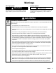
WARNING
The bleed-type master air valve (45) is required in
your system to relieve air trapped between this
valve and the pump after the pump is shut off.
Trapped air can cause the pump to cycle unexpect-
edly, resulting in serious injury, including amputa-
tion.
Connect the Air Supply Line
Connect a grounded air supply hose to the 1/2 npt(f)
port of the air manifold (37). Open the bleed-type
master air valve (45), and using the pressure
gauge (8), set the air regulator (13) to the desired
pressure. See Figure 1 and 2.
Pressure Relief Valve
Before operating the VRHC, make sure all compo-
nents have rated working pressures of 3000 psi
(21 MPa, 207 bar) or greater. For more information
about the pressure relief valve, see Instruction Manual
308547.