
User's Manual


16 309024
Operation
The pumps, mixer manifold and other components
were tested with lightweight oil at the factory. Before
operating the pump, thoroughly flush the VRHC to
prevent contamination of the fluids.
System Flushing
NOTE: Flush the mixer, hose and gun/valve often
enough to prevent fluid from reacting or curing in them.
Contact your fluid manufacturer for the effective pot life
of the fluid you are using.
1. Put the pump intake hoses of the feed pumps into
5 gallon (20 liter) containers of compatible solvent.
Refer to the fluid manufacturer’s recommenda-
tions.
2. Start the pump as explained below.
3. Do not install the spray tip/nozzle yet. Hold a metal
part of the gun/valve firmly to the side of a
grounded metal pail. Using the lowest possible
fluid pressure, trigger the gun/valve into the pail.
4. When clean solvent comes from the gun/valve,
release the trigger and carefully check all connec-
tions in the system for leaks.
5. Take the hoses out of the solvent and trigger the
gun/valve until all solvent has been pumped out of
the hoses.
Starting the Pump
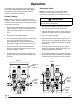
NOTE: To open the mixer manifold (120), put the
handle in the down position. To close the mixer
manifold, put the handle in the up position. See Fig. 7.
CAUTION
Never exceed 25% of the normal proportioner output
pressure with the feed system.
1. Start feed pump supplies and ensure fluid pres-
sure is at least 25 psi at each pump outlet.
2. Close the bleed-type master air valve. Turn the air
regulator knob all the way out (counterclockwise).
3. Turn on the main air supply.
4. Open the mixer manifold handle, trigger the gun/
valve, slowly open the bleed-type master air valve,
and turn the air regulator knob clockwise until the
pump starts.
5. Allow the pump to cycle slowly until all the air is
pushed out of the lines. Release the trigger – the
pump will stall against the pressure.
6. The manifold handle controls fluid flow. When the
manifold is open, base and catalyst are supplied to
the gun/valve. To stop the flow, close the handle.
02370
Fig. 7
Solvent
Solvent Out
Solvent
valve
shown
open
Base Catalyst
Base Catalyst
Solvent
Solvent
valve
shown
closed
Handle Up,
Mixer
Closed
Handle
Down,
Mixer
Open