
User's Manual


308642 7
Installation
Pre-Installation Procedure
1. Relieve the pressure.
WARNING
To reduce the risk of serious injury whenever you
are instructed to relieve pressure, always follow the
Pressure Relief Procedure on page 9.
2. Close the fluid shut-off valve (item J in Fig. 1).
3. Ground the hose and reel or console. See
Grounding on page 8. Do not use PTFE tape
on the pipe joints; it may cause a loss of ground
across the pipe joint.
Installation Procedure
CAUTION
If this is a new installation, or if the oil in the
lines is contaminated, flush the lines before you
install the dispensing valve.
New Installation
1. Relieve the pressure.
WARNING
To reduce the risk of serious injury, whenever you
are instructed to relieve pressure, always follow the
Pressure Relief Procedure on page 9.
Steps2to6aretheFlushing Procedure.
2. Close the fluid shut-off valve (J) at each dispense
position.
3. Make sure the main fluid outlet valve at the pump
is closed, the air pressure to the pump motor is
adjusted, and the air valve is open. Slowly open
main fluid valve.
4. Place the hose end (with no dispense valve con-
nected) into a container for waste oil. Secure the
hose in the container so it will not come out during
flushing. If you have multiple dispense positions,
first flush the dispense position farthest from the
pump, and work your way toward the pump.
5. Slowly open the shut-off valve (J) at the dispense
position. Flush out a sufficient amount of oil to
ensure that the entire system is clean, and close
the valve.
6. Repeat step 5 at all other dispense positions.
Existing Installation
1. Relieve the pressure.
WARNING
To reduce the risk of serious injury, whenever you
are instructed to relieve pressure, always follow the
Pressure Relief Procedure on page 9.
2. Loosen and disconnect the hose from the old
dispense valve (the one that you are replacing).
For steps 3 to 5, see Fig. 2.
3. Thread the extension (26a) into the outlet of the
dispense valve, and tighten firmly.
NOTE: Do not over tighten the extension tube
assembly by using the nozzle adapter to hand turn the
nozzel. For rigid extensions, thread the extension
in at least three full turns, position the extension
for proper alignment, and tighten the sealing
nut (7). The PTFE seal on the sealing nut must
face the valve housing.
4. Apply thread sealant to the male threads of the
hose fitting, thread the hose fitting into the swivel
(20), and tighten firmly.
5. Thread the new nozzle (8) or nozzle adapter onto
the extension, and tighten firmly.
6. Open all dispense position shut-off valves, and
start the pump to pressurize the system. See the
Operation section for proper operation.
7. For metered dispense valves, to ensure dispens-
ing accuracy, purge all air from the fluid lines and
dispense valves before you use them.
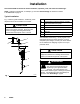
20
Model shown is a V12 with
a75_ bend rigid extension.
Fig. 2
26a
7
8
06292A