
User's Manual


308642 11
Service
NOTE: See instruction manual 307965 for electronic meter service instructions.
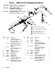
Valve Handle Repair
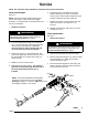
See Fig. 3.
NOTE: The large end of the pushrod (30) fits into a
notch in the cam (21), which is part of the trigger
assembly. It is important that you know this before you
remove or install parts.
1. Relieve the pressure.
WARNING
To reduce the risk of serious injury, when you are
instructed to relieve pressure, always follow the
Pressure Relief Procedure on page 9.
2. If you are replacing the o-rings (15), or the cam
(21), or the push rod (30), remove the swivel (20),
and remove the internal pieces. You must
remove the cam in order to get the push rod
out of the outlet end of the valve handle.
3. Remove the screws (14) and washers (28), and
remove the trigger (24). Push the cam (21) out of
the valve handle (18). Replace the o-rings (15)
and/or the cam.
4. Replace any worn or broken parts.
5. Reassemble the internal pieces. The push rod
(30) must be inserted through the outlet end of
the valve handle before the cam (21) is
installed.
6. Lubricate the cam, and slide it into the valve
handle, making sure the notch is oriented as
shown in Fig. 3. Ensure that the large end of the
pushrod is resting in the notch of the cam.
7. Replace the screws (14) and washers (28), and
torquethescrewsto15to25in-lb(1.7to
2.8 N-m).
8. Replace the swivel (20), and torque to 15 to 20
ft-lb (20 to 27 N-m).
Filter Replacement
See Fig. 3.
1. Relieve the pressure.
WARNING
To reduce the risk of serious injury, when you are
instructed to relieve pressure, always follow the
Pressure Relief Procedure on page 9.
2. Unscrew the hose fitting from the swivel (20).
3. Remove and replace the filter (10), which is inside
the valve handle (18). Make sure the filter is
oriented as shown in Fig. 3.
4. Thread the hose fitting into the swivel (20), and
tighten. Make sure the swivel (20) is torqued to
15 to 20 ft-lb (20 to 27 N-m).
Fig. 3
14
14
15
20
21
24
18
28
30
notch
15
28
10
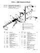
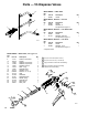
NOTE: For torque specifications and lubrication
instructions, see the service notes in the Parts
Drawings on pages 12, 13 and 14. EM6 models do not
have trigger lock parts 11, 25, and 27.
7854B
27
11
25