
User's Manual
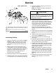

16 308345
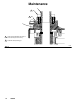
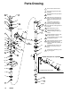
Parts Drawing
TI0301B
1
3
4
2
1
5
3
18
16 or 17
26
27
1
12
12a
22
5
6
41
24
25
24
25
4
8
7
46
50
44
20
45
21
11
11
9
32
34
33
2
10
13
14
15
14a
35
28
29
31
30
2
3
4
6
7
8
10
6
8
7
10
See Detail
39
27
30
11
11
56
11
12
12
9
9
Includes items 18a to 18e
18a
18c
18e
18d
18b
51
Needle Valve (Ref. No. 18) Detail
16a
Press into place; lips face down.
Apply high-strength thread sealant
to threads.
Apply anaerobic PTFE pipe sealant
to threads.
With helix tube (7) flush with top of
bushing (14), torque oppositely and
evenly to 55 to 60 in-lbs (6.2 to 6.8
Nm).
Tighten after you align pulleys
(12 and 13). Torque setscrew to
45 to 55 in–lbs (5.1 to 6.2 Nm).
Drive belt must not be tight after it is
installed.
Bend washer tab up to lock.
Apply PTFE spray lubricant to
inside lip of bearing nut before you
install it.
Torque oppositely and evenly to 80
to 100 in-lbs (9 to 11.3 Nm).
Torque oppositely and evenly to 60 to
70 in-lbs (6.8 to 7.9 Nm).
Apply PTFE spray lubricant to siphon
tube (4) inlet end and to top 6 in.
(150 mm) of helix tube (7) before you
install them.
Install flush with top of nut (8), and
torque to 40 to 45 in-lb (4.5 to 5.1
Nm).
5
Install with outer lips facing up. See
Fig. 8 on page 12.
13
13
3
3
3
3
3
51
3
0911B
18f