
User's Manual

308345 15
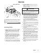
Service
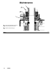
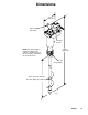
Fig. 10
12 22715
14a
14
13
With helix tube (7) flush with top of bushing (14), torque the
screws oppositely and evenly to 55 to 60 in-lbs (6.2 to 6.8 Nm).
Replace with a genuine ESD rated and marked belt only.
1
1
2
2
Model 236629 shown
03027B
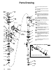
Assembling the Mixer
1. Make sure the spacer (10) is in place (see Parts
Drawing on page 16). With its larger-I.D. taper
facing up, install the larger pulley (13) and the
drive belt (15) through the mixer housing. See
Fig. 10.
2. Slide the other end of the drive belt over the
smaller pulley (12). The drive belt should not be
tight after it is installed. Make sure the pulleys are
aligned, then secure the small pulley (12) by
tightening its setscrew. Torque setscrew to
45 to 55 in–lbs (5.1 to 6.2 Nm).
3. Place the bushing (14) into the larger pulley (13).
4. Install the screws (14a) in the non-threaded holes
in the bushing (14); do not tighten the screws yet.
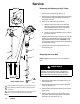
5. Place the installation tool (B) on the end of the
helix tube. See Fig. 9.
NOTE: The installation tool (B) is included with
Shaft Seal Kit 236762.
CAUTION
Use the installation tool (B) to insert the helix tube (7)
through the shaft seal (21) without damaging the seal
lip. See Fig. 9. See the Parts Drawing on page 16
for the location of the seal.
6. Apply PTFE spray lubricant to the top 6 in.
(150 mm) of the helix tube (7). While holding the
pulley (13) down, push the helix tube and tool (B)
up through the bottom of the mixer housing (3)
until the tube is flush with the top of the bushing
(14). Then remove the installation tool.
Wedge a screwdriver blade into the gap of the
bushing (14) to spread the bushing while inserting
tube (7).
7. Torque the three hex-head screws (14a) oppositely
and evenly to 55 to 60 in-lbs (6.2 to 6.8 Nm). See
Fig. 10.
8. Install the thrust washer (35) flush to the bushing
(14) as shown in Detail B of Fig. 9.
9. Secure the drive belt cover (2) with the eight
screws (27).
10. Apply PTFE spray lubricant to the siphon tube (4)
inlet end only. Install the siphon tube through the
top of the mixer housing (3). See Fig. 9.
11. Install the two socket-head screws (24) and lock-
washers (25) into the top of the siphon cover (6).
Torque the screws oppositely and evenly to 60 to
70 in-lbs (6.8 to 7.9 Nm).
NOTE: The helix tube (7) should move up and
down about 0.05 inch (1.3 mm). If it does not, the
bearings (11) are not fully seated. Push the bear-
ings in until they are fully seated. See the Parts
Drawing on page 16 for the location of the bear-
ings.
12. Apply PTFE spray lubricant to the inside lip of the
bearing nut (8), and tighten it onto the helix
tube (7).