INSTRUCTIONS-PARTS LIST This manual contains important warnings and information. READ AND KEEP FOR REFERENCE. 308–341 Rev. G Supersedes F First choice when quality counts. INSTRUCTIONS Optimiser 2K HVLP Two Component Adhesive Spray Gun 100 psi (7 bar) Maximum Working Fluid and Air Pressure This gun is for use with water-based contact adhesives only Part No. 949–239, Series C U.S. Patent Pending 02748 GRACO INC. P.O. BOX 1441 MINNEAPOLIS, MN COPYRIGHT 1993, GRACO INC. Graco Inc. is registered to I.
Table of Contents Warnings . . . . . . . . . . . . . . . . . . . . . . . . . . . . . . . . . . . . . . 2 Selection Chart . . . . . . . . . . . . . . . . . . . . . . . . . . . . . . . . 4 Air Flow and Atomizing Pressure . . . . . . . . . . . . . . . . . 5 Installation . . . . . . . . . . . . . . . . . . . . . . . . . . . . . . . . . . . . 6 Setup and Shutdown . . . . . . . . . . . . . . . . . . . . . . . . . . . 7 Ratio Check . . . . . . . . . . . . . . . . . . . . . . . . . . . . . . . . . .
WARNING PRESSURIZED EQUIPMENT HAZARD Spray from the gun, hose leaks or ruptured components can splash fluid in the eyes or on the skin and cause serious injury. Do not stop or deflect fluid leaks with your hand, body, glove or rag. Follow the Pressure Relief Procedure on page 7 when: you are instructed to relieve pressure; stop spraying; clean, check or servicing the equipment; and install or clean fluid nozzles. Never point the spray gun at anyone or at any part of the body.
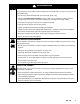
Selection Chart Includes: Needle/ Nozzle/Air Cap Kit P/N Needle Assembly P/N Air Cap P/N Nozzle P/N Replacement Needle Tip P/N Orifice Size 949–276 238–703 185–794 185–756 191–564 0.020” (0.508 mm) 949–277 238–703 185–794 185–757 191–564 0.026” (0.660 mm) 949–278 238–703 185–794 185–700 191–564 0.030” (0.762 mm) 949–279 238–217 185–794 185–701 191–016 0.042” (1.067 mm) 949–280 238–218 185–794 185–702 191–017 0.055” (1.
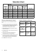
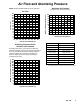
Air Flow and Atomizing Pressure NOTE: All tests completed with the fan air fully open. Atomizing Air Pressure (inlet pressure vs. atomizing pressure) 30 28 26 24 22 20 18 16 14 12 10 8 6 4 2 0 15 20 18 16 14 12 10 8 6 4 2 0 15 NOMINAL ATOMIZING PRESSURE (psi) AIR FLOW (scfm) Air Flow 25 35 45 55 65 75 85 95 GUN AIR INLET PRESSURE (psi) 25 35 45 55 65 75 85 95 GUN AIR INLET PRESSURE (psi) Gun Inlet Pressure Nominal Atomizing Pressure 15 psi (1.05 bar) 1.5 psi (0.
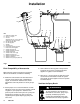
Installation E D G F N A S B R C M J H KEY A B C Optimiser 2K Spray Gun Air Inlet; 1/4 npsm Air Hose Recommend 5/16” (7.9 mm) ID hose; Optional 3/8” (9.
Installation Air Line Accessories Fluid Line Accessories The gun air line must have an air regulator (E) to control air pressure to the gun. See Fig. 1. If the gun air source does not have a filter, install a filter (F) on the gun air line to ensure a dry, clean air supply. To eliminate the need to shut off the air pressure at the air supply, install a quick-disconnect at the gun air inlet fitting.
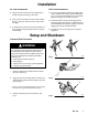
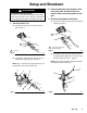
Setup and Shutdown Removing and Installing the Fluid Nozzle Follow this procedure whenever you remove and install a fluid nozzle. See page 4 to select a nozzle or needle/nozzle/air cap kit. 1. Follow the Pressure Relief Procedure on page 7. 3. Trigger the gun while you remove the fluid nozzle (20) with the gun wrench (35). 2 Trigger the gun whenever you tighten or remove the fluid nozzle (20) to pull the needle away from the nozzle seating surface and avoid scratching it. 4.
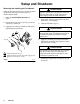
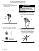
Setup and Shutdown WARNING EQUIPMENT MISUSE HAZARD This gun is for use with water-based contact adhesives only. Any other use of the gun could cause unsafe operating conditions or damage to the gun. 2. Flush the adhesive and activator fluid lines with water and blow them out with air before connecting them to the gun. 3. Connect the adhesive fluid hose. A. Connect the fluid hose (R) to the gun adhesive inlet (S). See Fig. 8. 1. Connect the air line. A. Connect the air hose (C) to the gun air inlet (B).
Setup and Shutdown 4. Connect the activator tube. 6. Adjust the spray pattern. WARNING A. Connect the fitting (V) and tube (M) to the gun activator inlet. See Fig. 10. B. Connect the other end of the fluid tube (M) to a regulated fluid supply line or a pressure tank. COMPONENT RUPTURE HAZARD Do not exceed the 100 psi (7 bar) maximum fluid and air pressure of this gun. Higher pressures can cause parts to rupture and result in serious injury.
Setup and Shutdown 6. Adjust the spray pattern. (continued) C. Hold the gun parallel to the floor and adjust the adhesive fluid pressure until you have a 1 to 6 inch (25.4 to 152.4 mm) straight fluid stream before the stream falls off. See Fig. 14. D. To further reduce the volume of adhesive output at the gun, turn the fluid adjustment knob (8) clockwise as needed. See Fig. 16.
Setup and Shutdown 6. Adjust the spray pattern. (continued) 7. Adjust the activator fluid flow. F. Set the gun air supply pressure at 40 psi (2.8 bar), using the gun atomizing air regulator (E). See Fig. 18. NOTE: Use the fluid manufacturer recommendations if available and refer to the Atomizing Pressure Versus Activator Inlet Pressure chart on page 5 when adjusting the gun. Local laws may limit the maximum pressure to 10 psi (0.7 bar) at the air cap for HVLP compliance.
Ratio Check 521 NOTE: You cannot sample the adhesive and activator at the same time. The adhesive must be checked with the atomizing air off, while the activator must be checked with the atomizing air on. 522 1. Check the ratio of the adhesive. 54 A. Weigh an empty beaker. B. Close the atomizing air shut-off valve. C. Close the activator shut-off valve. D. Trigger the gun into the beaker for 15 seconds to dispense the adhesive. E. Follow the Pressure Relief Procedure on page 7. F.
Daily Gun Care, Flushing, and Cleaning CAUTION Do not point the gun up while cleaning it as this may allow fluid to enter the gun air passages. C. Point the gun down into the spray booth* and spray until the water sprays clear. See Fig. 22. * If the gun is flushed with solvent, be sure to spray the solvent into a grounded metal waste container. Do not use metal tools to clean the air cap holes as this may scratch them and distort the spray pattern. Do not immerse the gun.
Daily Gun Care, Flushing, and Cleaning 3. Clean the gun. (continued) B. Disconnect the air supply line (C). See Fig. 24. C 02800 Fig. 24 C. Remove the air cap ring (12), air cap (19), air cap seal (47), and fluid nozzle (20) as instructed on page 8. 20 02775A Fig. 26 F. Clean the air cap ring, air cap, and fluid nozzle daily, minimum, using a soft-bristle brush. See Fig. 27. Clean out air cap holes with a soft implement, such as a toothpick, to avoid damaging surfaces. 35 47 12, 19 Fig.
Daily Gun Care, Flushing, and Cleaning 3. Clean the gun. (continued) G. Install the fluid nozzle (20) air cap seal (47), air cap ring (12), and air cap (19) as instructed on page 8. Fluid needle shaft Activator nuts, in the area where they contact the trigger Lubricate H. Dampen a soft cloth with soapy water; squeeze out the excess water. Point the gun down and wipe off the outside of it. Lubricate Lubricate 02782A Fig. 28 4. Lubricate the following gun parts daily, using Part No.
Troubleshooting PROBLEM CAUSE SOLUTION Fluid flow is fluttering while spraying 1. Fluid nozzle is not tight enough 1. See page 8 to install the fluid nozzle correctly 2. Fluid filter is clogged 2. Check the fluid filter 3. Fluid adjustment knob is not properly set 3. Adjust the fluid adjustment knob for less feathering or use a larger size nozzle 4. Baffle (item 11) is installed wrong or damaged 4.
Service 8. Insert a thin-blade screw driver (A) through the back of the gun and into the packing adjustment nut (31) and remove the screw. See Fig. 31. Items Needed for Service Gun Wrench – provided Seal Installation Tool – provided Adjustable Wrench Screw Driver Part No. 111–265 Lubricant A Soap and water 31 NOTE: Gun Repair Kit 949–285 is available; see page 25. The following procedure covers the replacement of all the kit parts. Disassemble 1.
Service 10. Use the threaded end of the fluid needle (21) to push out the u-cup seal (33). See Fig. 33. 11. Remove and disassemble the activator valve (49). See Fig. 34. Use the threaded end of the activator needle (49d) to push out the needle packings (49g and 49r). Do not bend the end of the needle. 12. Clean the parts. Check the fluid needles (21 and 49d) for damage or excessive wear. Replace if necessary. 21 13. Check the baffle (11) for damage.
Service Assemble NOTE: See Fig. 34, page 19, for the parts that need to be lubricated. A 31 1. Insert the fluid needle (21) through the front of the gun as shown in Fig. 35. Install the new packing assembly (39) by placing them on the end of the needle tip. Orientate the packings as shown in Fig. 35. 02762 Fig. 36 4. Place the new u-cup seal (33) on the seal installation tool (42) with the u-cup lips facing the tool. See Fig. 37. 1 2 5.
Service 6. Slide the new air valve (14) onto the fluid needle (21) until it is against the nut (B). See Fig. 38. 7. Install the fluid needle (21) and air valve (14) into the back of the gun. 9. Remove the u-cup seal (32) from the fluid adjustment nut (6). See Fig. 40. Do not damage the seal surface or the nut’s internal threads. 10. Place the new u-cup seal (32) on the seal installation tool (42) with the u-cup lips facing the tool. See Fig. 40. 11.
Service 13. Install the spring (15) and fluid adjustment nut (6). Tighten the nut to 25 to 35 in-lbs (2.8 to 4.0 N m). See Fig. 42. 18. Secure the activator valve (49) to the plate (2) with the two screws (53). Tighten the screws to 10 to 15 in-lbs (1.1 to 1.7 N m). 14. Install the spring (16) and fluid adjustment knob (8). 19. Place the o-ring (49e) in the groove on the plate (2). Lightly lubricate the o-ring, and slide the plate, with the activator valve assembly, onto the top of the gun body. 15.
Service 8 49m 49p 49j 2 49f 49d 49q 49h 49e 49r 49g 49c 49a 53 48 49k 9 49b 49 51 52 9 55 49e 7 2 12 19 49e 47 5 6 1 20 17 11 9 52 33 3 14 21 4 3 39 5 31 1 15 8 16 4 32 22 NOTE: See Fig. 34, page 19, for the parts that need to be lubricated. 1 Tighten to 25–35 in-lbs (2.8–4.0 N m) 2 Tighten to 10–15 in–lb (1.1–1.7 N.
Parts Drawing 49m 49p 49j Ref No. 13 Fan Air Valve Assembly Includes items 13a–13d 49q 49h 49r 49g 49b 49f 49d Ref No. 49 Activator Valve Assembly Includes items 49a–49r 49n 49e 49c 53 49a 49k 48 51 49 52 52 55 12 49e 2 19 47 49e 20 17 11 5 13d 13b 1 25 13c 13a 33 4 21 14 3 39 31 1 15 16 32 22 6 1 35 Tighten to 25–35 in–lb (2.8–4.0 N.m) NOTE: See the Service section for additional assembly information.
Parts List Part No. 949–239, Series C Optimiser 2K HVLP Spray Gun Ref No. Part No.
Technical Data Maximum Working Fluid and Air Pressure . . . . . . . . . . . . . . . . . . . . 100 psi (7 bar) Weight . . . . . . . . . . . . . . . . . . . . . . . . . . . 17.5 oz. (0.5 kg) Air Inlet . . . . . . . . . . . . . . . . . . . 1/4–18 npsm (R1/4–19) compound thread Adhesive Inlet . . . . . . . . . . . . . 3/8–18 npsm (R3/8–19) compound thread Activator Inlet . . . . . . . . . . . . . . . . . . . . . . . 1/8–27 npt(f) Wetted Parts Adhesive and Activator . . .
Notes
The Graco Warranty and Disclaimers Graco warrants all equipment listed in this manual which is manufactured by Graco and bearing its name to be free from defects in material and workmanship on the date of sale by an authorized Graco distributor to the original purchaser for use. With the exception of any special extended or limited warranty published by Graco, Graco will, for a period of twelve months from the date of sale, repair or replace any part of the equipment determined by Graco to be defective.