
User's Manual

Installation
Remote Monitoring When Meter is in a Class , Division 1 Hazardous Location
Models PPM 3050H, 3100H, and 3550H ONLY
WARNING
To
reduce the risk of fire and explosion and serious
injury:
Be sure to understand and follow
Hazardous
Location Wiring
of Intrinsically Safe Circuits
instructions.
When meter models PPM 3050H, 3100H, and
3550H are installed in a Class
I
, Division 1, Group
D hazardous location and a remote monitor is in a
non-hazardous location, a barrier module must be
used.
Hazardous
(classified)
Location Wiring of
Intrinsically Safe Circuits
The PPD 200 Remote Displays 235–613, 235–614,
and 235–615 have a barrier module installed. If using
another remote monitor
, see the
Safety Barrier Speci
-
fications
on page 22.
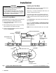
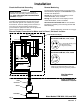
The PPD 200 Remote Display barrier module has 6
terminals. T
erminals 1 and 2 are for the non-hazardous
side connections. T
erminals 3 and 4 are the intrinsical
-
ly safe connections to the hazardous location.
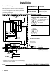
Wiring beyond terminals 3 and 4 should maintain at
least a 2 inch (50 mm) separation from any non-intrin
-
sically safe wiring and must be marked as Intrinsically
Safe Wiring at the required intervals. Field junction
boxes may be used as long as this separation is main
-
tained.
WARNING
The transmitting of flammable atmosphere from
one area to another through a multi-conductor
cable can cause fire or explosion and result in
serious injury and property damage. Follow the
instructions below and refer also to NEC Article
504 and 4.3 of ANSI standards ISA-RP12.6.
The cable must be sealed or vented at the point where
the cable enters and leaves the non-hazardous area.
(See
Accessories
for Graco cable seal, part no.
110–458.)
The purpose of such sealing or venting is to prevent
the cable from transmitting the flammable atmosphere
from one area of a hazardous location to another or
from a hazardous location to a non-hazardous location
at a rate of more than 198 cm
3
of air per hour (h) at a
pressure of 1493 Pa (0.007 ft
3
/h of air at a pressure of
6 in. of water), with both ends of the cable at atmo
-
spheric pressure.
Along with terminals 1, 2, 3, and 4, two extra screw
terminals are provided, one on each side of the barrier
.
They are conductively connected to the mounting rail
once properly installed.
Without grounding, Intrinsic Safety Barriers will not
provide voltage protection. Therefore, they must be
grounded to a designated grounding electrode. This
electrode should be the same potential as that used for
the non-hazardous location side instrumentation. The
ground conductor must be insulated from adjacent
grounded metal objects and no smaller than a #12
A
WG. The grounding path resistance from the barrier
to this ground point must not exceed 1 ohm.
For further information on installation and wiring, refer
to ANSI standards ISA-RP12.6
Installation of
Intrinsically Safe Systems for Hazardous (Classified)
Locations,
NEC
Article 504
and the
Canadian Electrical
Code Appendix F
.