
User's Manual

Installation
Remote Monitoring
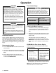
The
flow meter will send an output pulse for each gear
tooth that passes the sensor
. The actual K-factor for
your meter is marked on the data sheet included with
the meter
. The approximate flow volume per one pulse
(K-factor)
is shown at right.
METER MODEL NO. K-FACTOR
PPM
3050 & 3050H
0.1
136 cc per pulse
PPM 3100 & 3100H
0.2294 cc per pulse
PPM 3550 & 3550H
0.5883 cc per pulse
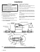
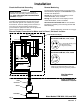
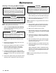
Remote Display Connections for Meter used in Class , Division 1 Location
Fig.
3
Cable Connector
(Pin Side
) for Meter
Models PPM 3050H, 3100H, & 3550H
1 +8–30 VDC Supply
(red)
2
Signal Out
(white)
3
Ground
(black)
4
not used
5
not used
Cable Connector
(Solder Side
) for Meter
Models PPM 3050H, 3100H, & 3550H
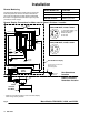
Sensor
Flow
Meter
Cable
Connector
#12
A
WG GREEN INSULATED WIRE
Must
connect to
true earth ground
0.47
F
CAPACITOR
PPD
200 Remote Display
Class , Division 1
Hazardous Location
Non-Hazardous
Location
* Cable
wire connections between meter and remote display
.
Other wiring is factory installed.
Meter Models PPM 3050H, 3100H, and 3550H
Intrinsic
Safety
Barrier