
User's Manual

Installation
Check the Electrical Grounding
WARNING
Proper
electrical grounding of your system is
essential. For your safety
, read the warning sec
-
tion,
FIRE, EXPLOSION, OR ELECTRIC SHOCK
HAZARD
, on page 2.
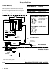
Have a qualified electrician check the electrical
grounding continuity between the flow meter sensor
and a true earth ground. If the resistance is greater
than 25 ohms, check the cable ground connection; re
-
fer to the Fig. 2 wiring schematic. Reconnect the
ground sheath or replace the cable. Do not operate the
system until the problem is corrected.
Remote Monitoring
The
flow meters are designed for use with the Graco
PPD 200 Remote Displays. See
Accessories for part
numbers and descriptions.
See Fig. 2 to connect the remote display to meter
models PPM 3050, 3100, and 3550.
See Fig. 3 to connect the remote display to meter
models PPM 3050H, 3100H, and 3550H.
See instruction manual 308–242
for more detailed
information on installing and connecting the PPD 200
Remote Display
.
Remote Monitoring continued on next page.
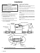
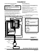
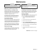
Remote Display Connections for Meter used in Class , Division 2 Location
Fig.
2
Sensor
Flow
Meter
Cable Connector
(Solder Side
) for
Meter Models PPM 3050, 3100, & 3550
A +10–30 VDC Supply
(red)
B
Ground
(black)
C
Signal Out
(white)
Cable
Connector
Cable Connector
(Pin Side
) for
Meter Models PPM 3050, 3100, & 3550
Class , Division 2
Hazardous Location
Non-Hazardous
Location
PPD
200 Remote Display
*
Cable wire connections between meter and
remote display
. Other wiring is factory installed.
Meter Models PPM 3050, 3100, and 3550