
User's Manual
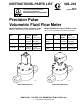

10308-243
Maintenance
Cleaning or Servicing the Meter Chamber
WARNING
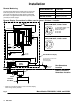
Installing
and servicing this equipment requires ac
-
cess to parts that may cause electric shock or oth
-
er serious injury if the work is not performed prop
-
erly
. Do not install or service this equipment unless
you are trained and qualified.
WARNING
Use only genuine Graco replacement parts. Sub
-
stitution of components may impair intrinsic safety
.
This could result in a failure which causes serious
injury and/or substantial property damage.
NOTE:
Clean and service the meter at a clean work
-
bench. Use only lint-free cloth on parts.
1.
Follow the
Pressure Relief Procedure W
arning,
on page 8. Then close the fluid shut-of
f valve on
each side of the meter
.
WARNING
Models PPM 3050, 3100, and 3550 only:
T
o reduce the risk of fire or explosion, DO NOT
disconnect the cable while the circuit is live unless
the location is known to be non-hazardous.
2.
Disconnect the cable from the electronic sensor
device.
3.
Disconnect both fluid line fittings and remove the
meter from the fluid line.
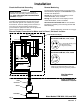
4.
Remove the electronic sensor device (1) from the
flow meter upper housing (2) by using a light
wrench on the sensor keyway
. Do not twist the
meter housings (2 & 3). Refer to Fig. 4.
5.
Loosen the hex bolts (9). Keep a few threads of
two opposing bolts engaged to minimize the torque
stress on the shafts when you separate the meter
housings.
6.
Hold onto the upper housing (2) and gently tap the
opposing bolts to separate the lower housing (3).
CAUTION
T
o avoid damaging the shafts (5), keep the hous
-
ings parallel to each other when separating them;
do not rock the housings from side to side. Do not
use chisels or screwdrivers to split and pry apart
the housings.
7.
Mark the positions of the gears (4) and shafts (5)
before removing them from the lower housing (3).
8.
Remove and inspect the gears (4) and shafts (5).
Clean the meter parts with solvent.
NOTE:
Replace the o-ring (8) whenever the meter is
disassembled.
9.
Reassemble the gears and shafts into the lower
housing in the position they were removed from.
Check the gears for free and easy rotation.
10.
Make sure the dowels (A) are in place.
11.
Align the index marks (B). Then assemble the two
meter housings, making sure to keep them parallel
to each other
.
12.
Install the hex bolts (9). T
ighten them oppositely
and evenly
, hand-tight (1
1 ft-lb [15 N
m]). Do not
over-tighten.
13.
After re-assembly
, test the gear rotation by apply
-
ing a brief air blast to the meter inlet. Y
ou should
clearly hear the gears spin.
14.
Models PPM 3050, 3100, & 3550:
Screw the elec
-
tronic sensor device into the meter hand-tight; do
not over-tighten.
Model PPM 3050H, 3100H, & 3550H:
Screw the
electronic sensor device all the way into the meter
,
then back of
f 1/4 turn and tighten the locknut; do
not over-tighten.
NOTE: A
void forcefully twisting the meter housings
during assembly
.